Download
1 / 32
320 likes | 347 Vues
Learn about the MYTHEN detector, its performance, and applications in powder diffraction experiments. Discover how the detector meets requirements for time-resolved experiments with high spatial resolution and large dynamic range.

E N D
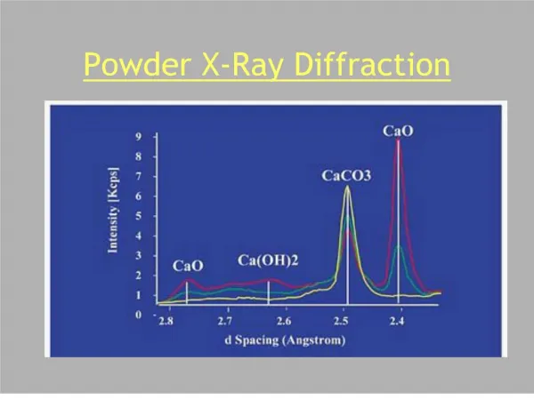
Photon counting microstrip detector for time resolved powder diffraction experiments A. Bergamaschi, A. Cervellino, R. Dinapoli, F. Gozzo, B. Henrich, I. Johnson, P. Kraft, A. Mozzanica, B. Schmitt, X. Shi
Outline • Powder diffraction detector requirements • Description of the MYTHEN detector • Detector performances • Example applications
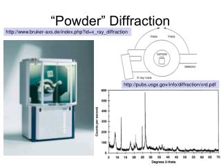
X-Ray beam Powder diffraction Bragg’s law 2q A powder contains “infinite” crystal orientations and the 3D of the reciprocal space collapse onto 1D
Detector requirements • Position of the peaks • size and dimension of the unit cell • Shape of the peaks • properties of the materials • High spatial resolution • Intensity ratios of the peaks • type and location of atoms • Large dynamic range
Time resolved experiments • Samples in a variable environment • Phase changes in the sample • Many cycles to check the reversibility of forms • Radiation sensitive samples • Organic samples degrade already after a few minutes of exposure • Pump and probe experiments • Gating and triggering to synchronize with stimulus
Silicon microstrip detector 120o acquired in parallel in fractions of a second Crystal analyzer detector Better than 0.003° resolution Angular selectivity Long measurements 15 min-several hours Silicon crystals Scintillator and photomultiplier Powder diffraction detectors monochromatic X-ray beam
MicrostripsYstem for Time rEsolvedexperimeNts • Silicon microstrip sensor • Position sensitive • 50 μm pitch • 1280 independent channels • Single photon counting readout • Large dynamic range • 24 bits • Poisson-like statistics
The wide angle diffractometer • Massive Parallel detection • 120o angular coverage • 30k independent channels • 0.03% bad • 0.004o angular resolution • Usually limited by the sample size • Time resolved powder diffraction is possible • Average acquisition time 1s • The acquisition can run 30000 faster than using the single channel crystal analyzer
Mythen Control System • Embedded Linux system • Client-Server TCP/IP communication • Real time data taking • Memory on board • External gating and triggering • Interfacing to external hardware • Pump and probe experiments
Readout time • Selectable counter dynamic range 4-24 bits
1 module 24 modules Frame rate • The maximum frame rate is limited by the data transfer rate from the MCS to the PC • Configurable number of modules to increase the frame rate
A correspondence between threshold value and X-ray energy should be found The threshold is normally set at half of the energy value The comparator threshold should correspond to the same energy for all channels Energy resolution Count uniformity Charge sharing Threshold Noise Energy Energy calibration
Comparator threshold linearity • Shaper and amplifier settings depending on the application • Standard • Emin = 8 keV • Fe=90% = 1 MHz • Fast • Emin = 10 keV • Fe=90% = 3 MHz • High gain • Emin = 5 keV • Fe=90% = 300 kHz • The comparator threshold is adjustable on a module base
Threshold dispersion The same voltage threshold does not correspond exactly to the same energy for all channels Trimming the threshold for each channel internally with the internal 6 bits DAC Count differences due to the charge sharing slope A threshold dispersion larger than the electronic noise ENC places a limit on the minimal detectable energy stot2=ENC2+sthreshold2 Emin=10 stot=15 keV
Trimming methods • Trimming with noise • 1 minute • sthreshold lower than ENC • Trimming with X-rays • Detector illumination by scanning in front of the beam • 45 minutes • sthreshold further improved
Count uniformity Energy=17.5keV Threshold=8.75keV • A flat field correction of the data is still necessary to obtain a Poisson-like statistic S=scounts2/ <counts>=1 • Suntrimmed = 2.6 • Simproved = 1.2 • A further improvement of the trimming is possible by optimizing the DAC dynamic range
Ritveld refinement • Structures can be determined from microstrip data
amorphous CoFeWB Co(Fe) + Co21B6W2 Crystallization of Co-rich alloysunder microwave field • Co-rich amorphous alloys for stable high temperature use as soft-magnetic nanomaterials • Single-pulse microwave field application • One-step nanocrystallization. Time (s) 2q (channel number) Courtesy of S. Vaucher
Conclusions • Calibration is essential for a proper operation of a large angular range detector • Energy calibration and trimming • Flat field correction • Angular calibration • The quality of the data acquired with the new Mythen detector is comparable to that obtained with the analyzer detector • Fast and time resolved measurements are also possible! • Not only Powder diffraction: Time resolved, pump and probe, FEMTO, Imaging, SAXS • Mythen is a unique detector for 1-D X-ray applications • Large diffraction systems for synchrotrons • Smaller systems available also for lab diffractometers (Dectris AG)
Perspectives • Faster data taking • 10 kHz for the single module • 1 kHz for the 24 modules • Higher intensities • Higher count rate (time over threshold mode) • Integrating readout under test • Higher spatial resolution • 25 mm pitch sensors wire-bonded on both sides • Higher efficiency • Thick sensors • High Z-materials • Mythen3 ASIC…
50 μm 300 μm The microstrip sensor • Direct conversion of X-rays into electric charge • The spatial resolution is defined by the 50 μm strip pitch
threshold 24 bit counter +1 Amplifier and Shaper Comparator Single Photon counting • High dynamic range • Essentially noiseless Low signal applications • No saturation High dynamic range From detector
Smaller systems 1 module 6 modules • Faster frame rate • Up to 600 fps 1 module - 4 bits
Expected spectra SpectrumThreshold scan
Loss of efficiency at high rates • Reference for X-ray intensity given by a IC or by the detector background counts Expected counts m extrapolated from fit at low intensities on measured data Counts measured counts n Intensity reference (A.U.)
threshold Efficiency vs. rate • Negligible efficiency loss up to 200 kHz (fast) • tfast~ 90 ns • tstandard~ 170 ns • thigh gain ~ 600 ns
Trimming with X-rays • X-ray energy set at the threshold level • Uniform illumination of the whole detector by scanning in front of an aperture • Starting from the noise settings the trimbits are changed in order to equalize the number of counts for each module • 45 minutes due to the detector movement (5 steps) • The threshold dispersion is reduced of a factor 15 • A further optimization of the DAC dynamic range is possible
Delay (ns) Channel number FEMTO commissioning gate electron bunch • The gating is needed only to separate the single bunch from the halo • The time resolution is defined by the length of the bunch • Each channel can count maximum 1 photon/bunch • Need for normalization between pumped and unpumped measurements time delay
Form B P 21 a=20.0175183 Å b=11.1227619 Å c=10.1091282 Å b=116.0562° Form B Coexistence of form A and form B Form A P 21 a=9.7618163 Å b=10.9467663 Å c=10.0000525 Å b=114.6366° P 21 a=9.7981196 Å b=10.9621025 Å c=10.0362587 Å b=114.8317° P 21 a=20.0635510 Å b=11.1291475 Å c=10.1380314 Å b=116.1898° P 21 (form A) a=9.8327528 Å b=10.9783448 Å c=10.0777516 Å b=115.0373° Form A at RT P 21 a=9.7197351 Å b=10.9304190 Å c=9.9642952 Å b=114.4349° P 21 (form B) a=19.9975732 Å b=11.1210824 Å c=10.0748662 Å b=115.894° Form A Sample in a variable enviroment • Structural solution of Bupivacaine (local anesthetic) • In-situ measurements in the furnace • Several cycles to check the reversibility of forms
Radiation damage Example of an organic sample from and industrial user before and after irradiation