SEMICONDUCTORS
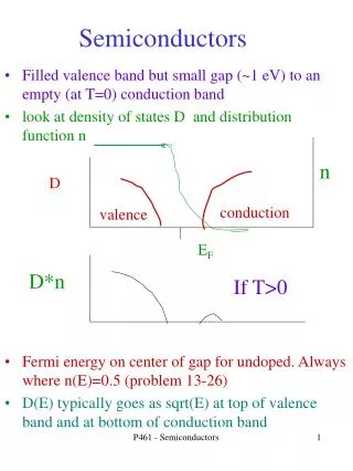
SEMICONDUCTORS. Electronic Materials. The goal of electronic materials is to generate and control the flow of an electrical current. Electronic materials include: Conductors : have low resistance which allows electrical current flow

SEMICONDUCTORS
E N D
Presentation Transcript
Electronic Materials • The goal of electronic materials is to generate and control the flow of an electrical current. • Electronic materials include: • Conductors: have low resistance which allows electrical current flow • Insulators: have high resistance which suppresses electrical current flow • Semiconductors: can allow or suppress electrical current flow A presentation of eSyst.org
Conductors • Good conductors have low resistance so electrons flow through them with ease. • Best element conductors include: • Copper, silver, gold, aluminum, & nickel • Alloys are also good conductors: • Brass & steel • Good conductors can also be liquid: • Salt water A presentation of eSyst.org
Copper Atom Conductor Atomic Structure • The atomic structure of good conductors usually includes only one electron in their outer shell. • It is called a valence electron. • It is easily striped from the atom, producing current flow. A presentation of eSyst.org
Insulators • Insulators have a high resistance so current does not flow in them. • Good insulators include: • Glass, ceramic, plastics, & wood • Most insulators are compounds of several elements. • The atoms are tightly bound to one another so electrons are difficult to strip away for current flow. A presentation of eSyst.org
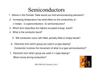
Semiconductors • Semiconductors are materials that essentially can be conditioned to act as good conductors, or good insulators, or any thing in between. • Common elements such as carbon, silicon, and germanium are semiconductors. • Silicon is the best and most widely used semiconductor. A presentation of eSyst.org
Semiconductor Valence Orbit • The main characteristic of a semiconductor element is that it has four electrons in its outer or valence orbit. A presentation of eSyst.org
Crystal Lattice Structure • The unique capability of semiconductor atoms is their ability to link together to form a physical structure called a crystal lattice. • The atoms link together with one another sharing their outer electrons. • These links are called covalent bonds. 2D Crystal Lattice Structure A presentation of eSyst.org
3D Crystal Lattice Structure A presentation of eSyst.org
Semiconductors can be Insulators • If the material is pure semiconductor material like silicon, the crystal lattice structure forms an excellent insulator since all the atoms are bound to one another and are not free for current flow. • Good insulating semiconductor material is referred to as intrinsic. • Since the outer valence electrons of each atom are tightly bound together with one another, the electrons are difficult to dislodge for current flow. • Silicon in this form is a great insulator. • Semiconductor material is often used as an insulator. A presentation of eSyst.org
Doping • To make the semiconductor conduct electricity, other atoms called impurities must be added. • “Impurities” are different elements. • This process is called doping. A presentation of eSyst.org
Semiconductors can be Conductors • An impurity, or element like arsenic, has 5 valence electrons. • Adding arsenic (doping) will allow four of the arsenic valence electrons to bond with the neighboring silicon atoms. • The one electron left over for each arsenic atom becomes available to conduct current flow. A presentation of eSyst.org
Resistance Effects of Doping • If you use lots of arsenic atoms for doping, there will be lots of extra electrons so the resistance of the material will be low and current will flow freely. • If you use only a few boron atoms, there will be fewer free electrons so the resistance will be high and less current will flow. • By controlling the doping amount, virtually any resistance can be achieved. A presentation of eSyst.org
Another Way to Dope • You can also dope a semiconductor material with an atom such as boron that has only 3 valence electrons. • The 3 electrons in the outer orbit do form covalent bonds with its neighboring semiconductor atoms as before. But one electron is missing from the bond. • This place where a fourth electron should be is referred to as a hole. • The hole assumes a positive charge so it can attract electrons from some other source. • Holes become a type of current carrier like the electron to support current flow. A presentation of eSyst.org
Types of Semiconductor Materials • The silicon doped with extra electrons is called an “N type” semiconductor. • “N” is for negative, which is the charge of an electron. • Silicon doped with material missing electrons that produce locations called holes is called “P type” semiconductor. • “P” is for positive, which is the charge of a hole. A presentation of eSyst.org
Current Flow in N-type Semiconductors • The DC voltage source has a positive terminal that attracts the free electrons in the semiconductor and pulls them away from their atoms leaving the atoms charged positively. • Electrons from the negative terminal of the supply enter the semiconductor material and are attracted by the positive charge of the atoms missing one of their electrons. • Current (electrons) flows from the positive terminal to the negative terminal. A presentation of eSyst.org
Current Flow in P-type Semiconductors • Electrons from the negative supply terminal are attracted to the positive holes and fill them. • The positive terminal of the supply pulls the electrons from the holes leaving the holes to attract more electrons. • Current (electrons) flows from the negative terminal to the positive terminal. • Inside the semiconductor current flow is actually by the movement of the holes from positive to negative. A presentation of eSyst.org
In Summary • In its pure state, semiconductor material is an excellent insulator. • The commonly used semiconductor material is silicon. • Semiconductor materials can be doped with other atoms to add or subtract electrons. • An N-type semiconductor material has extra electrons. • A P-type semiconductor material has a shortage of electrons with vacancies called holes. • The heavier the doping, the greater the conductivity or the lower the resistance. • By controlling the doping of silicon the semiconductor material can be made as conductive as desired. A presentation of eSyst.org
P type and N type semiconductors, taken separately are of very limited use. If we join a piece of P type material to a piece of N type material such that the crystal structure remains continuous at the boundary,,….. A PN JUNCTION is formed
It can function as …. Rectifier , Amplifier , Switching And other operations in electronic circuits.
A PN junction cannot be produced by simply pushing two pieces together or by welding etc…. Because it gives rise to discontinuities across the crystal structure. • Special fabrication techniques are adopted to form a P N junction
What is a PN Junction? A PN junction is a device formed by joining p-type ( doped with B, Al) withn-type (doped with P, As, Sb) semiconductors and separated by a thin junction is called PN Junction diode or junction diode.
Electronic Symbol …..the triangle shows indicated the direction of current P type N type Depletion layer forms an insulator between the 2 sides
In PN junction diode, N is at right and P is at left. • Majority carriers N region -- electrons P region -- holes
Formation of depletion layer NO external connections: the excess electrons in the N region cross the junction and combine with the excess holes in the P region. N region loses its electrons ……becomes + vly charged P region accepts the electrons ……becomes -vly charged At one point , the migratory action is stopped.
An additional electrons from the N region are repelled by the net negative charge of the p region. Similarly, • An additional holes from the P region are repelled by the net positive charge of the n region. • Net result a creation of a thin layer of each side of the junction ……….which is depleted (emptied) of mobile charge carriers…. This is known as DEPLETION LAYER ..Thickness is of the order of 10-6meter
The depletion layer contains no free and mobile charge carriers but only fixed and immobile ions. • Its width depends upon the doping level.. • Heavy doped……..thin depletion layer • lightly doped……..thick depletion layer
POTENTIAL BARRIER • The total charge formed at the p-n junction is called barrier voltage, barrier potential or junction barrier. • The size of the barrier voltage at the p-n junction depends on, the amount of doping, junction temperature and type of material used. The barrier voltage for silicon diode is 0.7 volts and for germanium is 0.3 volts. • The negative charge formed at the p-side of the p-n junction is called negative barrier voltage while the positive charge formed at the n-side of the p-n junction is called positive barrier voltage.
PN junction can basically work in two modes, (A battery is connected to the diode ) • forward bias mode ( positive terminal connected to p-region and negative terminal connected to n region) • reverse bias mode( negative terminal connected to p-region and positive terminal connected to n region)
Forward biased PN junction • It forces the majority charge carriers to move across the junction ….decreasing the width of the depletion layer.
Once the junction is crossed, a number of electrons and the holes will recombine . • For each hole in the P section that combines with an electron from the N section, a covalent bond breaks and an electron is liberatyed which enters the positive terminal • Thus creating an electron hole pair. • Current in the N region is carried by ….electrons • Current in the P region is carried by …. Holes.
Reverse biased pn junction • If the + of the battery is connected to the n-type and the – terminal to the p-type, the free electrons and free holes are attracted back towards the battery, hence back from the depletion layer, hence the depletion layer grows. Thus a reverse biased pn junction does not conduct current
Only the minority carriers cross the junction constituting very low reverse saturation current. • This current is of the order of micro ampere.
VOLTAGE –CURRENT (V-I) CHARACTERISTICS OF PN JUNCTION DIODE • The curve drawn between voltage across the junction along X axis and current through the circuits along the Y axis. • They describe the d.c behavior of the diode.
When it is in forward bias, no current flows until the barrier voltage (0.3 v for Ge) is overcome. • Then the curve has a linear rise and the current increases, with the increase in forward voltage like an ordinary conductor.
Above 3 v , the majority carriers passing the junction gain sufficient energy to knock out the valence electrons and raise them to the conduction band. • Therefore , the forward current increases sharply .
With reverse bias, • potential barrier at the junction increased. …junction resistance increase…and prevents current flow. • However , the minority carriers are accelarated by the reverse voltage resulting a very small current (REVERSE CURRENT)….in the order of micro amperes.
When revrese voltage is increased beyond a value ,called breakdown voltage,the reverse current increases sharply and the diode shows almost zero resistance .It is known as avalanche breakdown. • Reverse voltage above 25 v destroys the junction permanentaly.
Working of a PN junction Current I-V characteristic of a PN junction diode. Reverse Bias Forward Bias Zener or Avalanche Breakdown Voltage • PN junction diode acts as a rectifier as seen in the IV characteristic. • Certain current flows in forward bias mode. • Negligible current flows in reverse bias mode until zener or avalanche breakdown happens. Refer https://nanohub.org/resources/68 for a detailed discussion on operation of PN junction.
Thus the P N junction diode allows the electrons flow only when P is positive . • This property is used for the conversion of AC into DC ,Which is called rectification
Automatic switch • When the diode is forward bias ,the switch is CLOSED. • When it is reverse biased , it is OPEN
ADVANTAGES: • No filament is necessary • Occupies lesser space • Long life.
APPLICATIONS • ….as rectifiers to convert AC into DC. • As an switch in computer circuits. • As detectors in radios to detect audio signals • As LED to emit different colours.