Download
1 / 16
160 likes | 349 Vues
Enrico Calloni Federico II Univ. - Naples on behalf of the Virgo collaboration MG12, July 13 2009, Paris. Status of the Virgo interferometer. Commissioning timeline. May '07 - Sep '07 First Virgo Science Run (VSR1) Oct '07 - May '08 Commissioning

E N D
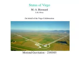
Enrico Calloni Federico II Univ. - Naples on behalf of the Virgo collaboration MG12, July 13 2009, Paris Status of the Virgo interferometer
Commissioning timeline • May '07 - Sep '07 First Virgo Science Run (VSR1) • Oct '07 - May '08 Commissioning • Scattered light mitigation: replaced brewster window by cryotrap • TCS installation, mirror magnets strength reduction • 9 May '08 Vacuum viewport failure • May - Oct '08 Virgo+ shutdown • Injection system, infrastructure and electronics upgrade • NE payload recovery, replacement of all viewports • Oct '08 – July ‘09 Commissioning • Remaining electronics upgrade • Commissioning with more input power and TCS • New Global Control • 7 Jul '09 Start Second Virgo Science Run (VSR2) • 2010 Monolithic suspension upgrade? This talk
Incident recovery • Caused by weak design of view-port, identified and tested safer model • Replaced about 90 view-ports throughout whole interferometer • Cleaned and tested North-End tower • New payload at North-End: coating of already polished spare mirror
Virgo+ upgrade: infrastructure • Replaced complete wiring of main power and grounding in central building • Replaced and doubled UPS • Replaced 15 kV transformer • New hot water pipes • Lowered speed of air-conditioning
Virgo+ upgrade: injection system • New laser amplifier: up to 50 W (25 W at interferometer input) • New pre-mode-cleaner • Remotely tunable in-vacuum Faraday Isolator • Heavier input-mode-cleaner end-mirror
Virgo+ upgrade: electronics • Replaced real-time fiber links: more flexible signal routing • Replaced old RIOs by real-time PC: much more computing power • New ADCs: from 16 to 18 bit • New quadrants read-out electronics for alignment
Interferometer restart • Interferometer no longer showed bi-stability during lock acquisition • Different working point: modulation frequency changed by 700 Hz • Maybe caused by slightly different radius of curvature of new mirror
Thermal Compensation System • Annulus and central spot from CO2 laser on both input mirrors • Essential for compensating thermal lensing in input mirrors when working with high input powers • Not yet stabilized in amplitude, some evidence for introduced noise
Phase camera field amplitude phase between fields • Beam scanned on pinhole detector, signal demodulated to separate carrier and sidebands • Located on dark fringe before output-mode-cleaner (B1p) • Extensively used, but more as 'amplitude camera' • TCS fine alignment, 'cold interferometer' experiments • Mirror cool-down experiments to measure coating absorption
High power operation • Power increased in steps from 8 W (VSR1) to 17 W now • limited by thermal aberrations of input mode cleaner • No major problems with interferometer stability • Some alignments loops more critical • Quadrature signals (B1_ACq or B5_ACq) kept close to zero using slow servos on TCS power • Currently about 1.5 W on both mirrors: interferometer similar to 8W • 'Cold interferometer' with about 2x 6W • More optical gain, ideal frequency stabilization TF, but TCS too noisy without TCS with TCS
Sensitivity May 2007: ~3 Mpc July 2009: ~8 Mpc Sensitivity at VSR1 start (black) and VSR2 start (red)
Noise budget • Low frequency • Some environmental • Some scattering • Laser bench resonances • Actuator noise • No control noise! • Medium frequency • Mirror thermal noise • Shot noise • Detection bench resonances • TCS radiation pressure? • High frequency • Shot noise
Robustness Locking duty cycle : 97.4% (update at July 12 ) Science Mode duty cycle: 94.9% Interventions in “adjusting mode” are visible
Future work • During the run (commissioning breaks) • Damp external bench resonance (sorbothane) • TCS power stabilization? • Replace detection output window, with AR coating? • More noise hunting • Long term • Monolithically suspended mirrors, finesse 50 -> 150
Concluding • Robust interferometer • 95% Science Mode duty cycle • Good sensitivity • Stable horizon: 8-8.5 Mpc (1.4-1.4 Ns-Ns) - averaged 42-44 Mpc (10-10 BH-BH) - averaged • fluctuating with input mirror etalon effect • Low glitch rate: factor 10 lower than VSR1 • Preparing for installation of monolithic suspensions