Download

1 / 59
1.1k likes | 2.04k Vues
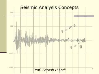
Seismic analysis of Bridges Part I. Introduction.

E N D
Introduction The evaluation of the risk associated to the seismic vulnerability of the transportation infrastructure, and in particular to that of bridge structures has been the object of quite large number of researches. This has stimulated the authorities to think about a code expressly dedicated to bridges. • In Italy, two are the seismic events in which bridges suffered important damages • Friuli Earthquake (1976) with limited damages have been observed in the bridges • IrpiniaEarthquake (1980) the bridges on the Highway A16 suffered some damages, essentially due to inadequacy of the bearing devices, which has been changed with isolation devices
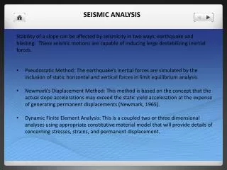
Introduction A proper seismic design have to start from the analysis of the behaviour of the structures during seismic events. Typicalobserveddameges are: Insufficient length of the supports Pounding between adjacent spans Insufficient design of the bearings Kobe Earthquake 1995 Nishinomiya-ko LomaPrietaEarthquake 1989 Cypressviaduct
Introduction A proper seismic design have to start from the analysis of the behaviour of the structures during seismic events. Typicalobserveddameges are: Insufficient length of the supports Pounding between adjacent spans Insufficient design of the bearings Kobe Earthquake 1995 Nishinomiya-ko LomaPrietaEarthquake 1989 Cypressviaduct
Introduction A proper seismic design have to start from the analysis of the behaviour of the structures during seismic events. Typicalobserveddameges are: Insufficient length of the supports Pounding between adjacent spans Insufficient design of the bearings Insufficient design of piers San Fernando Earthquake 1971 Higashi-Kobe
Introduction The damages of the piers are often due to the lack of ductility and/or shear strength of the sections Gothic Avenue Viaduct, Northdridge 1994 Wushiviaduct Chi-Chi, Taiwan 1999 Gothic Avenue Viaduct
Introduction The damages of the piers are often due to the lack of ductility and/or shear strength of the sections Gothic Avenue Viaduct, Northdridge 1994 Wushiviaduct Chi-Chi, Taiwan 1999 Gothic Avenue Viaduct
Introduction The damages of the piers are often due to the lack of ductility and/or shear strength of the sections ShinkansenViaduct Kobe, 1995
Introduction Example of complete collapse UrbanViaduct Hanshin, Kobe 1995
Seismiccodes In Europe the Eurocodes system includes a normative document for the seismic design of new bridges, which is at least partially based on the recent concepts of performance-based design: Eurocode 8 Part 2. For the existing structures there is the Eurocode 8 part 3 that regards only existing buildings. In Italy two main documents regards design of new bridges OPCM 3441 NTC 2008 Within a wide research program funded by RELUIS and in particular from the research line 3 (existing bridges) new guidelines of existing bridges has been proposed.
Seismiccodes • The philosophy of the new seismic codes includes the definition of performance levels mainly related to the importance of the structure (performance-based design) • The safety requirements and the limit states • Definition of the seismic input: • Elastic Spectra • Natural records and artificially generated accelerograms) - Scaling and combination rules • Evaluation of the safety level • Structural models • Analysis Methods (linear and non-linear static and dynamic analysis) • Evaluation of the members capacity • Verification Format
Seismiccodes • The philosophy of the new seismic codes includes the definition of performance levels mainly related to the importance of the structure (performance-based design) • The safety requirements and the limit states • Definition of the seismic input: • Elastic Spectra • Natural records and artificially generated accelerograms) - Scaling and combination rules • Evaluation of the safety level • Structural models • Analysis Methods (linear and non-linear static and dynamic analysis) • Evaluation of the members capacity • Verification Format
Safetyrequirements and LS The safety (protection level) is defined for a specific limit state for a given seismic level intensity characterized by a probability of occurrence PVR in a given time (Nominal Life VR). The nominal life depends on the type of construction (provisional, ordinary, strategic) The probability of occurrence is defined by the Return Period TR
Safetyrequirements and LS Distribution of the number of earthquakes (x) in a given interval of time t (Poisson distribution) is mean rate of occurrence of the events (probability of occurrence in the unit time) and is equal to the inverse of the arrival time Tr = 1/ Tr Probability of occurance of an earthquake with intensity S < Sa Probability of occurrence of an earthquake with intensity S > Sa is the complementary probability
Safetyrequirements and LS: Return Period Comment: This determinist approach contains actually the random nature of the earthquake. The most probable earthquake it considered
Safetyrequirements and LS: Limit States FEMA 356 ULS SLS
Safetyrequirementsand LS : Limit States FEMA 356 Operational level For non-strategic bridges only the Life Safety or Collapse prevention have to be verified, whereas for strategic bridges the SLD o SLO have also to be taken into account
Safetyrequirementsand LS : Limit States In EN1998:1 only 3 limit states are required (the operational level is missed) EN1998:1
Safetyrequirements and LS Evaluation of the return period of bridges following NTC08: (ReturnPeriod)
Safety requirements and LS Example 1: return Period calculation Evaluation of the return period of an ordinary bridge, for the SLV limit state (Life Safety) following NTC08: Nominal life: Vn> 50 Years (ordinary bridge) class: II VR = CUVn = 1 x 50 = 50 years Probability of occurrence : Pr = 10% Tr = - 50 / ln0.9 = 475 years Example 2: return Period calculation Evaluation of the return period of a strategic bridge, for the SLD and SLV limit states Nominal life: Vn> 100 Years (strategic bridge) class: IV VR = CUVn = 2 x 100 = 200 years SLV: Probability of excedence: Pr = 10% Tr = -200/ln0.9=1898 years SLD: Probability of excedence: Pr = 63% Tr = -200/ln0.37=201 years
Seismic Input : responsespectra Lo spettro di risposta Per il progetto di una struttura soggetta ad un terremoto, generalmente non è necessario conoscere l’intera storia temporale della forza Fs, quanto piuttosto il suo valore massimo. Ciò è possibile costruendo degli Spettri di Risposta elastici. Uno spettro elastico è definito come quel diagramma che in funzione del periodo proprio della struttura e dello smorzamento, fornisce il valore massimo di uno dei parametri della risposta dell’oscillatore elementare. Spettro di risposta in pseudo-accelerazione
Seismic Input : responsespectra Lo spettro di risposta La costruzione di uno spettro di risposta ad un determinato terremoto, può essere facilmente effettuata calcolando per la risposta massima di un oscillatore elementare al variare del periodo proprio e dello smorzamento. m m m k1 m k2 m k3 xg
Seismic Input : responsespectra Lo spettro di risposta: Caratteristiche • per T=0 (strutture rigide) lo spostamento Sd è nullo • Per T= (strutture flessibili) lo spostamento Sd è pari allo spostamento sul terreno • Esiste una zona entro la quale lo spostamento subisce un amplificazione • All’aumentare dello smorzamento l’amplificazione dimunuisce • per T=0 (strutture rigide) Sa è pari all’accelerazione sul terreno • Per T= (strutture flessibili) Sa è nulla • Esiste una zona entro la quale Sa subisce un amplificazione che in rapporto all’acc. sul terreno può variare tra 2 e 3 • All’aumentare dello smorzamento l’amplificazione dimunuisce
Seismic Input : responsespectra (EN1998-1: General rules, seismic actions and rules for buildings) Usually the seismic intensity is defined starting from the seismic hazard of the site in which the bridge has been built, expressed in terms of response spectrum. Horizontalspectra (EC8) Importancefactor ag = agR, S=soilfactor, =dampingcorrectionfactor Hazard
Seismic Input : responsespectra (EN1998-1: General rules, seismic actions and rules for buildings)
Seismic Input : responsespectra (EN1998-1: General rules, seismic actions and rules for buildings)
Seismic Input : responsespectra (EN1998-1: General rules, seismic actions and rules for buildings) Ground Types
Seismic Input : responsespectra (EN1998-1: General rules, seismic actions and rules for buildings)
SeismicInput : responsespectra (EN1998-1: General rules, seismic actions and rules for buildings)
Seismic Input : responsespectra (EN1998-1: General rules, seismic actions and rules for buildings) IMPORTANCE FACTOR FOR BRIDGES (SUGGESTED VALUES)
Seismic Input : responsespectra (NTC 08) The parameters of the elastic spectra are defined according to seismic hazard defined in terms of return period, which if function of the adopted performance level. The return period is defined with reference to a very refined grid (10 km x 10 km ) N.B.: the importance factor is not explicitally defined but is included in the definition of the importance classes Elasticspectrum
Seismic Input : responsespectra (NTC 08) Barberino del Mugello, Italy
Seismic Input: responsespectra (NTC 08) In order to verify the bridge supports or the application of the displacement-based design approach, elastic spectrum of displacements can be defined starting from the acceleration spectrum. Displacementspectrum
Seismic Input : accelerograms (NTC 08) • For time-history analyses the base motion is represented by natural or artificially generated accelerograms. In any case the following coherence condition has to be respected: • From EC8: “no value of the mean 5% damping elastic spectrum, calculated from all time histories, should be less than 90% of the corresponding value of the 5% damping elastic response spectrum” • For the artificially generated accelerograms additional conditions have to be respected: • The duration of the accelerograms shall be consistent with the magnitude and the other relevant features of the seismic event • The minimum duration Ts of the stationary part of the accelerograms should be equal to 10 s. • The minimum number of natural record is 10 and artificial accelerogram is 5
Seismic Input : accelerograms (NTC 08)
Seismic Input : accelerograms (NTC 08)
Seismic Input: accelerograms (NTC 08) An example of selection of natural records Target elasticspectrum Listofselectednaturalrecords (10 dir x +10 dir y)
Seismic Input: Combination (NTC 08, EN1998:1) In tridimensional problems, in order to get the maximum response quantities we need to combine the responses to the earthquakes in the all the three principal directions. For this purpose we can adopt two different formulas (only for elastic analysis. For non-linear analysis the maximum response in both directions is taken SRSS method 100-30-30 method
Structural ModelingMaterialmodels: concrete – Kent & Park Confinement parameters sh Parabolic Linear
Structural ModelingMaterialmodels: concrete – Popovic - Mander Confinement tension For the definition of this constitutive law is enough to know strength fc and elastic modulus Ec, for non-confined concrete, and also the transversal geometrical percentage of reinforcement and the relative yielding fy
Structural ModelingMaterialmodels: concrete – Popovic - Mander Parameters governing the confinement tension hc Dc bc
Structural ModelingMaterialmodels: Steel – Menegotto Pinto Model MP : used non-linear dynamic analysis EP : used in monotonic static analysis
Structural ModelingStiffness of Elements For the elements of the deck (beams, transverses, slabs, etc..) the stiffness is related to the no-cracked elastic behaviour of the sections When linear or non-linear analysis with plastic hinges are used the stiffness of the piers has to be calculated using the characteristics of the cracked sections MR (N) is the ultimate moment of the section calculated for a normal force due to the gravity load, usually calculated using the moment curvature relationship