Download
1 / 31
310 likes | 679 Vues
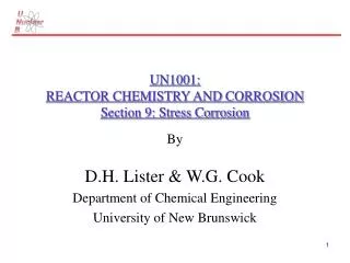
UN1001: REACTOR CHEMISTRY AND CORROSION Section 9: Stress Corrosion. By D.H. Lister & W.G. Cook Department of Chemical Engineering University of New Brunswick. UN1001: Section 9: Stress Corrosion. STRESS CORROSION (“Stress Corrosion Cracking” - SCC)

E N D
UN1001:REACTOR CHEMISTRY ANDCORROSIONSection 9: Stress Corrosion By D.H. Lister & W.G. Cook Department of Chemical Engineering University of New Brunswick
UN1001: Section 9: Stress Corrosion STRESS CORROSION(“Stress Corrosion Cracking” -SCC) Under tensile stress, and in a suitable environment, some metals and alloys crack . . . usually, SCC noted by absence of significant surface attack . . . occurs in “ductile” materials.
UN1001: Section 9: Stress Corrosion “Transgranular” SCC (“TGSCC”) Cross section of stress-corrosion crack in stainless steel.
UN1001: Section 9: Stress Corrosion “Intergranular” SCC (“IGSCC”) Intergranular stress corrosion cracking of brass.
UN1001: Section 9: Stress Corrosion Two original classic examples of SCC: • “season cracking” of brass; • “caustic embrittlement” of CS; both terms obsolete.
UN1001: Section 9: Stress Corrosion “Season Cracking” Occurs where brass case is crimped onto bullet, i.e., in area of high residual stress. Common in warm, wet environments (e.g., tropics). Ammonia (from decomposition of organic matter, etc.) must be present. Season cracking of German ammunition.
UN1001: Section 9: Stress Corrosion “Caustic Embrittlement” Early steam boilers (19th and early 20th century) of riveted carbon steel. Both stationary and locomotive engines often exploded. Examination showed: • cracks or brittle failures around rivet holes; • areas susceptible were cold worked by riveting (i.e., had high residual stresses); • whitish deposits in cracked regions were mostly caustic (i.e., sodium hydroxide from chemical treatment of boiler water); • small leaks at rivets would concentrate NaOH and even dry out to solid. SCC revealed by dye penetrant. Carbon steel plate from a caustic storage tank failed by caustic embrittlement.
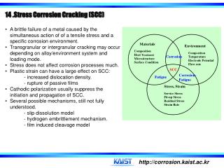
UN1001: Section 9: Stress Corrosion Factors important in SCC: • environmental composition; • stress; • metal composition and microstructure; • temperature; e.g.,brasses crack in NH3, not in Cl-; SSs crack in Cl-, not in NH3; SSs crack in caustic, not in H2SO4, HNO3, CH3COOH, . . . etc. }necessary
UN1001: Section 9: Stress Corrosion STRESS The greater the stress on the material, the quicker it will crack. (N.B. in fabricated components, there are usually RESIDUAL STRESSES from cold working, welding, surface treatment such as grinding or shot peening, etc., as well as APPLIED STRESSES from the service, such as hydrostatic, vapour pressure of contents, bending loads, etc.).
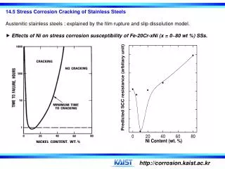
UN1001: Section 9: Stress Corrosion Composite curves illustrating the relative stress-corrosion-cracking resistance for commercial stainless steels in boiling 42% magnesium chloride. DISCUSS: how would you obtain such a curve and what does it mean?
UN1001: Section 9: Stress Corrosion The MAXIMUM stress you can apply before SCC is formed (c.f. MINIMUM stress to be applied compressively to prevent SCC) depends on alloy (composition and structure), temperature, and environment composition. Such “THRESHOLD” stresses may be between 10% & 70% of the yield stress - Q.V. N.B. residual stresses from welding steel can be close to the yield point. N.B. corrosion products can induce large stresses by “wedging”.
UN1001: Section 9: Stress Corrosion N.B. small-radius notch tip and even smaller-radius crack tip are STRESS RAISERS A “wedging action” by corrosion products of 10 ksi (10,000 psi) can induce 300 ksi (300,000 psi) at the crack tip.
UN1001: Section 9: Stress Corrosion Corrosion product wedging “denting” of S.G. tubes in some PWRs . . . Boiling in crevice concentrates impurities- can lead to acid + Cl- at seawater-cooled sites. “Hour-glassing” of Alloy-600 tubes led to severe straining and cracking of tubes.Surrey PWR in U.S. was first to replace S.Gs., because of denting.
UN1001: Section 9: Stress Corrosion Time to Failure Major damage during SCC occurs in late stages as cracks progress, cross-sectional area decreases, stress increases until final failure occurs by mechanical rupture.
UN1001: Section 9: Stress Corrosion Environmental Factors No general pattern, SCC common in aqueous solutions, liquid metals; also found in fused salts, nonaqueous inorganic liquids . . . N.B. Coriou (France) cracked Inconel-600 in pure water at 300C in 1959!!!
UN1001: Section 9: Stress Corrosion Environments that may cause stress corrosion of metals and alloys Material Environment Material Environment Aluminum alloys NaCl-H2O2solutions Ordinary steels NaOH solutions NaCl solutions NaOH-Na2SiO2 solutions Seawater Ca, NH3, and NaNO3 Air, Water vapor solutions Copper alloys NH3 (g & aq) Mixed acids (H2SO4-HNO3) Amines HCN solutions Water, Water vapor Acidic H2S solutions Gold alloys FeCl3 solutions Seawater Acetic-acid-salt solutions Molten Na-Pb alloys Inconel Caustic soda solutions Stainless steels Acid chloride solutions Lead Lead acetate solutions such as MgCl2and BaCl2 Magnesium alloys NaCl-K2CrO4 solutions NaCl-H2O2 solutions Rural and coastal Seawater atmospheres H2S Distilled water NaOH-H2S solutions Monel Fused caustic soda Condensing steam from Hydrofluoric acid chloride waters Hydrofluosilicic acid Titanium alloys Red fuming HNO3, N2O4, Nickel Fused caustic soda seawater,methanol-HCI
UN1001: Section 9: Stress Corrosion Increasing temperature accelerates SCC: Most susceptible alloys crack 100C;Mg alloys crack at room temperature. Alternate wetting and drying may aggravate SCC - accelerate crack growth (possibly because of increasing concentration of corrosive component as dryness is approached). Effect of temperature on time for crack initiation in types 316 and 347 stainless steels in water containing 875 ppm NaCl.
UN1001: Section 9: Stress Corrosion Some Data for Recommending Service of CS or Ni Alloy in Caustic NACE caustic soda chart super-imposed over the data on which it is based. Area A: Carbon steel, no stress relief necessary; stress relieve welded steam-traced lines; Area B: Carbon steel; stress relieve welds and bends; Area C: Application of nickel alloys to be considered in this area; nickel alloy trim for valves in areas B and C.
UN1001: Section 9: Stress Corrosion Metallurgical Factors inIGSCC In austenitic SS and Ni alloys, sensitization is of major importance in determining susceptibility to IGSCC . . . depletion of grain boundaries in Cr because of carbide precipitation makes them vulnerable to attack. e.g.,IGSCC of recirculation piping in BWRs (type 304 SS) induced by 200 ppb dissolved oxygen in the otherwise pure H2O coolant resulted in a major replacement problem. Plants using L-grade experienced very much less SCC. Al alloys (e.g., with Mg and Zn) are also susceptible to IGSCC because of precipitation within grain boundaries . . . Mg-rich precipitates can denude the grain boundaries of Mg, make them susceptible to attack in aqueous media. N.B. In grain-boundary-precipitate mechanisms for inducing IGSCC, very local galvanic effects between precipitates and matrix are important: • some precipitates are ANODIC; • some precipitates are CATHODIC.
UN1001: Section 9: Stress Corrosion Grain boundary segregation of alloy constituents or impurities (without precipitation of separate phases) can also induce IGSCC. e.g.,Mg enrichment of grain boundaries in Al alloys is a factor in IGSCC • promotes local dissolution and hydrogen entry (maybe to form hydride, MgH); • also . . . grain boundary enrichment of impurities and/or C in Fe-base alloys,Ni-base alloys and austenitic stainless steels can contribute to IGSCC; - segregation of P, Si, S, N, B reported; only clear link with IGSCC reported for P in austenitic SS in oxidizing aqueous solutions, for P in ferritic alloys in nitrate and caustic solutions.
UN1001: Section 9: Stress Corrosion Transgranular SCC Lattice structure in metal/alloy matrix important: dislocation emergence, movement along slip planes under stress, and similar factors that can disrupt passivating films, will promote dissolution of metal at highly localized and strained areas. Irradiation-Assisted SCC (IASCC) Since 1987, some in-reactor components have cracked in LWRs . . generally in core-support structures at the top of the vessel (austenitic SS, Ni alloys). More widespread in BWRs than PWRs . . . radiolytic chemical species (especially oxidizing radicals) seem to be the cause. IASCC of Alloy-600 (Inconel) penetrations in several PWR vessel heads have led to leaks and boric-acid corrosion of RPV head steel (e.g., Davis Besse). Heads replaced.
UN1001: Section 9: Stress Corrosion Mechanism of SCC SCC is very complex;probably no single mechanism, but several operating at the same time. Models (scientific descriptions) of mechanisms of two types: • dissolution; • mechanical fracture. Dissolution Models of Crack Propagation Major model is based on Film Rupture . . . (“slip-dissolution”) . . . high stresses at crack tip create local area of plastic deformation -ruptures passive films, exposed metal dissolves rapidly . . . some say periodic dissolution and re-passivation, some say crack tip always bare.
UN1001: Section 9: Stress Corrosion periodic rupture Schematic representation of crack propagation by the film rupture model.
UN1001: Section 9: Stress Corrosion Mechanical Fracture Models of Crack Propagation Corrosion Tunnel; • Corrosion tunnel models. • Schematic of tunnel model showing theinitiation of a crack by the formation of corrosion tunnels at slip steps and ductile deformation and fracture of the remaining ligaments. • (b) Schematic diagram of the tunnel mechanism of SSC and flat slot formation.
UN1001: Section 9: Stress Corrosion • Adsorption of impurities at the crack tip promotes the nucleation of dislocations; • lead to shear-like fracture (seemingly brittle). • Tarnish Rupture; Cracks propagate by alternate film growth and (brittle) film fracture, followed by rapid film formation over exposed metal. • Film-Induced Cleavage; • thin film forms; • brittle crack initiates in layer; • crack moves from film into matrix; • crack continues through ductile matrix until it blunts and stops; • process repeats. • Adsorption-Induced Brittle Fracture; Species adsorbing at crack tip alter inter-atomic bond strengths, lower stress required for fracture; propagation should be continuous. • Hydrogen Embrittlement; Cathodic processes involving hydrogen-ion reduction can inject H into matrix . . . this can embrittle metal, promote cracking . . . most likely in ferritic steels but also possible in Ni-base, Ti and Al alloys (contributes to SCC of carbon steel feeders at Point Lepreau …?).
UN1001: Section 9: Stress Corrosion Prevention of SCC 1. Lowering the stress below the threshold value if one exists.This may be done by annealing in the case of residual stresses, thickening the section, or reducing the load.Plain carbon steels may be stress-relief annealed at 590 to 650C, and the austenitic stainless steels are frequently stress-relieved at temperatures ranging from 820 to 930C. 2. Eliminating the critical environmental species by, for example, de-gasification, demineralization, or distillation. 3. Changing the alloy is one possible recourse if neither the environment nor stress can be changed.For example, it is common practice to use Inconel (raising the nickel content) when type 304 stainless steel is not satisfactory.Although carbon steel is less resistant to general corrosion, it is more resistant to stress-corrosion cracking than are the stainless steels.Thus, under conditions which tend to produce stress-corrosion cracking, carbon steels are often found to be more satisfactory than the stainless steels.For example, heat exchangers used in contact with seawater or brackish waters are often constructed of ordinary mild steel.
UN1001: Section 9: Stress Corrosion 4. Applying cathodic protection to the structure with an external power supply or consumable anodes.Cathodic protection should only be used to protect installations where it is positively known that stress-corrosion cracking is the cause of fracture, since hydrogen embrittlement effects are accelerated by impressed cathodic currents. 5. Adding inhibitors to the system if feasible.Phosphates and other inorganic and organic corrosion inhibitors have been used successfully to reduce stress-corrosion cracking effects in mildly corrosive media.As in all inhibitor applications, sufficient inhibitor should be added to prevent the possibility of localized corrosion and pitting. 6. Coatings are sometimes used, and they depend on keeping the environment away from the metal - for example, coating vessels and pipes that are covered with insulation.In general, however, this procedure may be risky for bare metal. 7. Shot-peening (also known as shot-blasting) produces residual compressive stresses in the surface of the metal.Very substantial improvement in resistance to stress corrosion found as a result of peening with glass beads.Type 410 stainless was exposed to 3% NaCl at room temperature; type 304 to 42% MgCI2 at 150C; and aluminum alloy 7075-T6 to a water solution of K2Cr2O7-CrO3-NaCl at room temperature.
UN1001: Section 9: Stress Corrosion Corrosion Fatigue The fatigue fracture of a metal aggravated by a corrosive environment or the stress corrosion cracking of a metal aggravated by cyclic stress. N.B. Fatigue fracture usually occurs at stresses belowthe yield point but after many cyclic applications of the stress. Typical “S-N” curves:
UN1001: Section 9: Stress Corrosion Fatigue-fractured material often shows most of the fracture face shiny metallic, with the final area to fracture (mechanically by brittle fracture of a reduced cross-section) having a rough crystalline appearance . . . If corrosion-fatigue occurs, the “shiny-metallic” area might be covered with corrosion products;BUT normal fatigue fractures may also develop corrosion products - depends on environment, stress pattern, etc.
UN1001: Section 9: Stress Corrosion N.B. In normal fatigue, the frequency of the stresscycles is not important. (can do accelerated fatigue tests at high frequency - the total number of cycles determines fatigue). BUT in corrosion fatigue, low-cycle stresses are more damaging than high-frequency stresses. Environment is important…. e.g.,in seawater: • Al bronzes and type 300 series SS lose 20-30% of normal fatigue resistance; • high-Cr alloys lose 60-70% resistance. N.B. Cyclic loads mean lower allowable stresses, this must be designed into components;if there is also a corrosive environment, the allowable stresses are EVEN LOWER.
UN1001: Section 9: Stress Corrosion Prevention of Corrosion Fatigue • change design so as to reduce stress and/or cycling. • reduce stress by heat treatment (for residual stress), shot peening (to change surface residual stresses to COMPRESSIVE). • use corrosion inhibitor with care! • use coatings . . . electrodeposited • Zn; • Cr; • Ni; • Cu; and • nitrided layers (heating of steels in contact with N-containing materiale.g., NH3, NaCN, etc.).