Download
1 / 24
240 likes | 258 Vues
This study focuses on the Low Energy Ring (LER) Pipetron as a pre-accelerator in the Large Hadron Collider (LHC) tunnel. Collaborations with FNAL and CERN are aimed at identifying benefits and challenges of implementing the pre-accelerator. The LHC's limitations due to multipole fields and beam quality necessitate a compact, cost-effective solution for pre-acceleration. The feasibility study examines space requirements and proposes experiment bypass options to optimize LER integration with the LHC. Key study subjects include optics, beam transfer, magnet design, and injection schemes, with a focus on efficient particle acceleration and transfer.

E N D
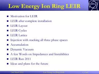
Low Energy Ring:Pipetron use in the LHC • Framework and Collaboration • LHC limits • Global description Low Energy Ring • Subjects on study at the moment • LER Workshop 3rd Upgrade-Machine-Experiment-interface meeting LER G. de Rijk
Framework and Collaboration Aim of the study: To find out what can be gained with, and whether there are show-stoppers for a pre-accelerator in the LHC tunnel Collaboration: • FNAL Henryk Piekarz , John Johnstone, Steven L. Hays, Yuenian Huang, Tanaji Sen, Vladimir Shiltsev • CERN Lucio Rossi, Gijs de Rijk 3rd Upgrade-Machine-Experiment-interface meeting LER G. de Rijk
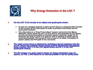
LHC Limits • LHC will be limited in bunch intensity and emittance due to the multipole fields at the injection plateau and by the quality of the beam coming from the injectors • The large ‘swing’ of the machine 0.45 TeV => 7 TeV 0.53 T => 8.34 T is the cause of sizable persistent currents in the cables. • Persistent currents in cables give rise to multipolar fields. These currents are not stable and this causes the ‘snapback’ of e.g. the b3 during the beginning of the ramp • These effects should be smaller at a higher injection energy (between 1 Tev-1.5 TeV instead of 0.45 TeV) and a shorter injection plateau (e.g. few ms instead of 20 min) 3rd Upgrade-Machine-Experiment-interface meeting LER G. de Rijk
Pre-accelerator LER • Pre-accelerator of 0.45 TeV => 1 TeV-1.5 TeV in the LHC tunnel. • Small transverse dimensions • Cheap • Using VLHC ‘pipetron’ magnets. • Inject all bunches into the LER, accelerate and transfer to the LHC in one go 3rd Upgrade-Machine-Experiment-interface meeting LER G. de Rijk
Pipetron - VLHC magnets FNAL VLHC • 0.45 TeV injection at 0.48 T • 1.5 TeV top at 1.595 T (55KA) • Gradient ~ 4% • Enlarged magnet aperture v 30 mm x h 40 mm LER 3rd Upgrade-Machine-Experiment-interface meeting LER G. de Rijk
Pipetron - VLHC magnets FNAL • 1 m prototype tested at FNAL • Reported at MT19 3rd Upgrade-Machine-Experiment-interface meeting LER G. de Rijk
Feasibility study - tunnel space Fits above the LHC ring (some cabling exceptions in straight sections) 3rd Upgrade-Machine-Experiment-interface meeting LER G. de Rijk
Feasibility study - tunnel space 3rd Upgrade-Machine-Experiment-interface meeting LER G. de Rijk
Feasibility study - tunnel space 3rd Upgrade-Machine-Experiment-interface meeting LER G. de Rijk
The challenge: Experiment bypasses There are: 2 large (ATLAS & CMS) 2 less big (ALICE & LHCb) experiments to bypass For this study we assume that after an upgrade only ATLAS and CMS will remain 3rd Upgrade-Machine-Experiment-interface meeting LER G. de Rijk
Experiment bypass options • Bypass the experiments in a tunnel • typically be ~300 long • Digging a bypass requires to empty the main tunnel at the junctions • An extra shaft is probably needed for each bypass • ==> at least a year shutdown • Bypass the experiments through the detectors • Drilling a hole through the detectors is probably a very bad idea • Bypass the experiments through the LHC beampipe • Bump beam down (and back up) into beam experimental beam pipe • Study concentrates on this option 3rd Upgrade-Machine-Experiment-interface meeting LER G. de Rijk
Injection / bypass scheme 3rd Upgrade-Machine-Experiment-interface meeting LER G. de Rijk
Subjects being studied • Optics • Combined function lattice • Beam size => required aperture • Matching • Impedance, instabilities, dynamic aperture • Batch coalescing to increase bunch intensity (x 2) • Beam transfer LER => LHC • Transfer positions • Magnets • Fast switched Vertical bending magnets (~3 ms) • Vertical septum magnets • Vertical bends • Dumping system and detector protection 3rd Upgrade-Machine-Experiment-interface meeting LER G. de Rijk
Injection / bypass scheme (2) 3rd Upgrade-Machine-Experiment-interface meeting LER G. de Rijk
Optics (1) • Arc cells match the LHC length • 4 Combined function magnets (12 m) per half cell Bmax 1.595 T, G = ± 4.969 T/m • Dispersion suppressor with separated function magnets (8 m dipoles and 3 m quads). • Straight sections have 4 m long quads • Low beta insertion is common with the LHC J. Johnstone FNAL 3rd Upgrade-Machine-Experiment-interface meeting LER G. de Rijk
Optics (2) J. Johnstone FNAL Correctors SSS 3rd Upgrade-Machine-Experiment-interface meeting LER G. de Rijk
Transfer between LER and LHC (1) • Horizontal separation 150 ==> 0 mm • Vertical separation 1350 ==> 0 mm • One fast switched magnet • horizonal bend 2 is made by tilting the vertical bends 3rd Upgrade-Machine-Experiment-interface meeting LER G. de Rijk
Transfer between LER and LHC (2) 3rd Upgrade-Machine-Experiment-interface meeting LER G. de Rijk
Timing sequence • Ramp up time from 0.45 TeV to 1.5 GeV is 100 s. • Fast pulsed magnets ramps down to 20% in 3 ms 3rd Upgrade-Machine-Experiment-interface meeting LER G. de Rijk
Fast switched magnets Option 1 Magnetic design by Vadim Kashikhin FNAL 3rd Upgrade-Machine-Experiment-interface meeting LER G. de Rijk
Beam dump and protection • Use separate kicker magnets to send beam to LHC dump. • Misfiring fast magnets: send beam into collimators in front of the experiments 3rd Upgrade-Machine-Experiment-interface meeting LER G. de Rijk
Possible schedule Time[y] Total[y] • LER accelerator design, including transfer lines 1 1 • Prototyping and testing transfer line magnets • (and main arc dipole magnet, if needed) 2 2 • Preparation of main arc magnet industrial production 1 2 • Magnet production 3 5 • Magnet installation in the tunnel 2 5 • LER commissioning 1 6 Items 1–3 and the items 4-5 can proceed simultaneously, The overall lapsed time for the LER completion work will be determined, however, by the number of months per year allowed for the LER installation, We assumed that 20 crews of 6 people should be able to install 40 magnets per week, or 1200 magnets in 30 weeks (~8 month). In summary, the LHC operation with the LER as injector could be ready in 6 years from the time “zero”. 3rd Upgrade-Machine-Experiment-interface meeting LER G. de Rijk
LER Workshop WEB page: http://ler06.web.cern.ch/LER06/ also on indico • LER workshop Wednesday 11 Oct (AT auditorium bld 30-7-18) • Full presentations of the studies done at FNAL • Discussion session at 15h45 3rd Upgrade-Machine-Experiment-interface meeting LER G. de Rijk
Conclusions • The main difficulty is the transfer between the LER and LHC rings • Match both optics • Fast switched magnets • Detector protection • LER has only one application : fill the LHC at 1 TeV -1.5 TeV (no fixed target physics) • It is very challenging, but not impossible • Up to now it is a study and not a proposal 3rd Upgrade-Machine-Experiment-interface meeting LER G. de Rijk