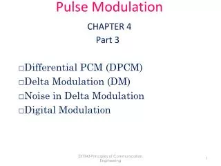
Figure 4-1 ADPCM (adaptive differential pulse code modulation)
Difference. 2 4 5 7 9 5 2 4 5 7. Figure 4-1 ADPCM (adaptive differential pulse code modulation). LECs Local Exchange Network. International Carriers. Business PBX Customer Premises Equipment. Interexchange Carriers. Internet Service Providers.
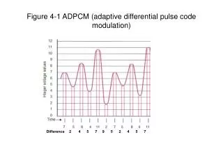

Figure 4-1 ADPCM (adaptive differential pulse code modulation)
E N D
Presentation Transcript
Difference 2 4 5 7 9 5 2 4 5 7 Figure 4-1 ADPCM (adaptive differential pulse code modulation)
LECs Local Exchange Network International Carriers Business PBX Customer Premises Equipment Interexchange Carriers Internet Service Providers Cellular Providers Residential Customer Local Loop Figure 4-2 Local exchange network
SMS London 203 New York 204 NCP Paris 202 Johannesburg 205 Auckland 201 NCP – Network Control Point SMS – Service Management System - IXC POP SMS Figure 4-3 Virtual Private Network
Interoffice Signaling Switch Switch Loop Signaling Figure 4-4 Interoffice Signaling
LEC Central Office LEC Central Office IXC Tandem IXC Tandem A B C D E F Phone off hook Call Setup Communicating Call termination Send dial tone Receive and translate digits Seize trunk Disconnect . Translate digits Seize trunk Disconnect Translate digits Seize trunk Disconnect Receive digits Ring phone Disconnect Phone answered Hang up Figure 4-5 Call Setup and Transmission
LEC Central Office LEC Central Office IXC Tandem IXC Tandem A B C D E F Switch B’ Switch E’ SSP SSP STP Note: Voice path and signal path separate Database SCP Switch B’ is located at CO B Switch E’ is located at CO E Figure 4-6 Call setup using common channel signaling
SSP STP STP Signaling Links SSP STP STP SSP = Service Switching Point STP = Signal Transfer Point SCP = Service Control Point SCP SCP Figure 4-7 SS7 Architecture
OSI Layer SS7 Layer 7 Application ____________ 6 Presentation ____________ 5 Session ____________ 4 Transport ____________ 3 Network ____________ 2 Data Link ____________ 1 Physical OA&M Network Applications 4 3 2 1 TCAP ___________ Presentation ___________ Session ___________ Transport ISDN Service User Part ISUP SSCP (Signaling Connection Control Part) Network Service Part MTP Signaling network _____________________________ Signaling Link _____________________________ Signaling data link TCAP = Transaction Capabilities Application part OA&M = Operations, Administration & Maintenance MTP = Message Transfer Part Figure 4-8 SS7 Layers Compared with the OSI Reference Model
Trunks to Other COs Line and Trunk Interfaces ALI - Analog Line Interface DLI - Digital Line Interface ATI - Analog Trunk Interface DTI - Digital Trunk Interface RLI - Remote Line Interface TDM - Time Division Multiplexer CPU - Central Processing Unit PS - Program Store CS - Call store Switch Features ACT - Automatic Coin Telephone AMA - Automatic message accounting ANI - Automatic Number Identification LIT- Line Insulation Test System LMS - Local Message Metering System MCC - Maintenance Control Center TMS - Transmission Measuring System TTS - Trunk Testing System Remote Line Interface Analog Phone Digital Phone ISDN Phones FAX PBX ALI DLI ATI DTI RLI CPU PS CS MCC Test monitor CPU TDM TDM Class 5 Switch Components Figure 4-9 A Digital Central Office
SSP IP STP SS7 Network CO CO Central Office SSP Service Switching Point STP Signal Transfer Point SCP Service Control Point IP Intelligent Peripherals SCP Customer Systems Figure 4-10 An AIN (Advanced Intelligent Network)
Operator Console LEC FGA (line side) LEC FGB (trunk side) PBX Tandem Switch IMT FEX Tandem Switch Phone FGD LATA DAL IMT Intermachine trunk DAL Dedicated access line FEX Foreign exchange FGA Feature group A FGB Feature group B FGD Feature group D LEC = End Office LEC LEC Figure 4-11 IXC Tandem Switch Architecture
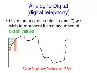
Quantizing Noise Figure 4-1 Digitizing a Voice signal
Primary Fiber Clockwise DLC Administrator Protect Fiber Counter-clockwise SONET Multiplexer SONET Multiplexer DLC Administrator Figure 4-5 SONET/SDH Architecture
High Speed High Speed OC-48 2.5 Gbps OC-48 2.5 Gbps Low Speed DS-1 1.54 Mbps to OC-12 622 Mbps Low Speed High Speed DS-1 1.54 Mbps to OC-3 155 Mbps Add/Drop Multiplexer OC-48 2.5 Gbps Terminal Multiplexer Figure 4-6 Terminal Multiplexers and Add/Drop Multiplexers
OSI Layers Application Presentation Session Transport Network Data Link Physical 7 6 5 4 3 2 1 OA&M Network Applications TCAP Presentation Session Transport ISDN Service User Part ISUP SSCP (Signaling Connection Control Point) Network service part Signaling network Signaling Link Signaling data link TCAP = Transaction Capabilities Application part OA&M = Operations, Adminiaration & Maintenance MTP = Message Transfer Part M TP Figure 4-8 SS7 Layers Compared with the OSI Reference Model