Download
1 / 6
60 likes | 94 Vues
Learn how to maximize the functionality of elementary building blocks like inverters, AND, and OR gates, D flip-flops to create complex circuits. Explore constructing registers, shift registers, and n-bit adders with proper glue logic. Discover the significance of primary and cascading inputs/outputs and explore examples showcasing the potential of these building blocks. Unleash your creativity in circuit design!

E N D
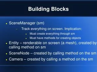
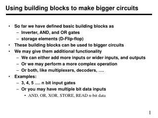
Using building blocks to make bigger circuits • So far we have defined basic building blocks as • Inverter, AND, and OR gates • storage elements (D-Flip-flop) • These building blocks can be used to bigger circuits • We may give them additional functionality • We can either add more inputs or wider inputs, and outputs • Or we may perform a more complex operation • Or both, like multiplexers, decoders, …. • Examples: • 3, 4, 5 …. n bit input gates • Or you may have multiple bit data inputs • AND, OR, XOR, STORE, READ n-bit data
D0 D1 D2 D3 D Q D Q D Q D Q Q0 Q1 Q2 Q3 C P C P C P C P Clock Making a register • Flip-flops can be connected to act as a register • All clock signals are connected together to one clock • All flip-flops get different input, each storing one-bit information • A 4-bit register is shown -- It uses 4 D-FFs • Has a 4 bit inputs and 1 clock and produces 4 bit output
D0 D Q D Q D Q D Q Q0 Q1 Q2 Q3 C P C P C P C P Clock Making a shift-register • Flip-flops can also be connected to act as a shift register • All clock signals are connected together to one clock • First flip flop gets a new input • Others get input from previous flip-flop • A 4-bit shift register is shown • It has one bit and one clock input and produces 1 bit output
A B C S Using 1-bit building blocks to make n-bit circuit • Design a 1 bit circuit with proper “glue logic” to use it for n-bits • It is called a bit slice • The basic idea of bit slice is to design a 1-bit circuit and then piece together n of these to get an n-bit component • Previous two examples showed how to use 1-bit components • However, there was no other glue signal or logic • Next, we consider other kind of examples • A half-adder adds two 1-bit inputs • Two half adders can be used to add 3 bits • A 3-bit adder is a full adder
A B C S A A1 A2 A0 A3 A C B B Cout0 Cout2 Cout1 Cout3 Cout Full Adder Full Adder Full Adder Full Adder Full Adder B0 B B3 B1 B2 Sum0 Sum Sum3 Sum2 Sum1 C1 C3 C Ci C2 Cout C C S S Sum Full adder and multi-bit adder • Two half adders can be used to add 3 bits • n-bit adder can use full adders • n can be arbitrary large
Glue Logic • Normally the glue logic is part of 1-bit adder • A basic building block has • Primary inputs • Primary outputs • Cascading inputs • Cascading outputs • The cascading signals interact directly with the glue logic • Carry in 1-bit adder is a primary as well as a cascading output • A and B are primary inputs • C is a cascading input • Cout is cascading output • S is primary output