Download
1 / 7
70 likes | 177 Vues
This document provides an extensive overview of the 40-6003” check valve, detailing its production history which began in 1992 and ended for the 3”-10” model in 2003. Important procedures for check cover removal, check valve removal, seat removal, and disc replacement are outlined, emphasizing the necessity of verifying spring load and using a special tool for seat removal. The guide concludes with reassembly instructions, highlighting the importance of lubricating o-rings during the process to ensure proper function.

E N D
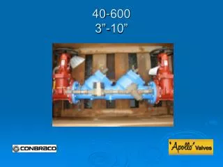
Modification Overview • Production of the 40 series began in 1992. • The 3”-10” 40-600 was discontinued in 2003. • The 40-600 used a ¾” 40-100 for the bypass assembly.
Check Cover Removal • Cover is o-ring sealed. • Loosen bolts 3/8”. Spring load is now released from the cover and retained by the check assembly. ** Verify spring load before removing all the bolts.
Check Valve Removal • Center stem guided check assembly. • Slide subassembly straight out of seat and body.
Check Seat Removal • 3”-8” sizes are threaded into the body and o-ring sealed. **A special tool is required to remove the seat. • 10” size is bolted into the body and o-ring sealed.
Check Disc Replacement • 3”-6” remove the nut and retaining plate. • 8”-10” remove the retaining plate bolts and retaining plate.
Check Valve Reassembly Notes • Reassemble check valves in reverse order. • Apply lubricant to o-rings.