Overview of MPEG Video Encoding and Decoding Structure
This document details the structure of MPEG video encoding and decoding, focusing on the combination of Discrete Cosine Transform (DCT) and motion-compensated interframe prediction. It explains how the coder generates a prediction error by subtracting motion-compensated predictions from source images. The prediction error is transformed using DCT, quantized, and encoded using Variable-Length Coding (VLC). It also describes how the decoder reconstructs and processes these coefficients to produce the final decoded video signal, with a focus on the video bitstream structure and accompanying graphical figures for clarity.

Overview of MPEG Video Encoding and Decoding Structure
E N D
Presentation Transcript
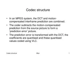
Codec structure • In an MPEG system, the DCT and motion-compensated interframe prediction are combined. • The coder subtracts the motion-compensated prediction from the source picture to form a ’prediction error’ picture. • The prediction error is transformed with the DCT, the coefficients are quantised and these quantised values coded using VLC. tMyn
The coded luminance and chrominance prediction error is combined with ’side information’ required by the decoder, such as motion vectors and synchronising information, and formed into a bitstream for transmission. • Figure 1 shows a simplified structure of a MPEG 2 encoder, Figure 2 that of a MPEG 2 decoder and Figure 3 shows an online of the MPEG 2 video bitstream structure. tMyn
VIDEO SIGNAL IN Discrete Cosine Trasnsform Variable-Length Coder Quantisation CODED BITSTREAM OUT Inverse Quantisation Inverse Discrete Cosine Transform Motion- Compensated Prediction Figure 1. Motion-compensated DCT encoder. tMyn
Inverse Quantisation Inverse Discrete Cosine Transform Motion- Compensated Prediction CODED BITSTREAM IN Variable-Length Decoder DECODED VIDEO SIGNAL OUT Figure 2. Motion-compensated DCT decoder. tMyn
In the decoder, the quantised DCT coefficients are reconstructed and inverse transformed to produce the prediction error. • This is added to the motion-compensated prediction generated from previously decoded pictures to produce the decoded output. tMyn
quantised DCT coefficients for one 8*8 block (variable length coded) Block layer Macroblock layer containing four luminance and two chrominance blocks for 4:2:0 video optional quantisation value coded block pattern motion vectors macroblock address luminance blocks chrominance blocks mode Slice layer containing n macroblocks macroblock 1 quantisation value macroblock 0 macroblock n-1 start code slice address … picture flags start code Picture layer containing m slices slice m-1 slice 0 slice 1 … Sequence layer containing p pictures optional quantisation weighting matrix picture p-1 start code sequence parameters profile and level picture 1 … picture 0 Figure 3. Outline of MPEG 2 video bitstream structure shown bottom up. tMyn
In Figure 3 each picture is divided into m horizontal slices, each comprising n macroblocks. • For 4:2:0 video, each macroblock contains four luminance and two chrominance 8*8 blocks of quantised DCT coefficients. tMyn