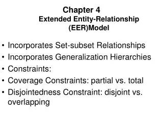
THE EXTENDED ENTITY RELATIONSHIP MODEL
THE EXTENDED ENTITY RELATIONSHIP MODEL. As the complexity of the data structures being modeled has increased and as application software requirements have become more stringent, there has been an increasing need to capture more information in the data model.

THE EXTENDED ENTITY RELATIONSHIP MODEL
E N D
Presentation Transcript
As the complexity of the data structures being modeled has increased and as application software requirements have become more stringent, there has been an increasing need to capture more information in the data model. • The extended entity relationship model (EERM), sometimes referred to as the enhanced entity relationship model, is the result of adding more semantic constructs to the original entity relationship (ER) model. • As you might expect, a diagram using this model is called an EER diagram (EERD). • In the following sections, you will learn about the main EER model constructs—entity supertypes, entity subtypes, and entity clustering—and see how they are represented in ERDs.
Entity Supertypes and Subtypes • Because most employees possess a wide range of skills and special qualifications, data modelers must find a variety of ways to group employees based on employee characteristics. • For instance, a retail company could group employees as salaried and hourly employees, while a university could group employees as faculty, staff, and administrators. • The grouping of employees to create various types of employees provides two important benefits: • It avoids unnecessary nulls in the employee attributes when some employees have characteristics that are not shared by other employees. • It enables a particular employee type to participate in relationships that are unique to that employee type.
To illustrate those benefits, let’s explore the case of an aviation business. • The aviation business employs pilots, mechanics, secretaries, accountants, database managers, and many other types of employees. • Figure 5.1 illustrates how pilots share certain characteristics with other employees, such as a last name (EMP_LNAME) and hire date (EMP_HIRE_DATE). • On the other hand, many pilot characteristics are not shared by other employees. • For example, unlike other employees, pilots must meet special requirements such as flight hour restrictions, flight checks, and periodic training. • Therefore, if all employee characteristics and special qualifications were stored in a single EMPLOYEE entity, you would have a lot of nulls or you would have to make a lot of needless dummy entries. • In this case, special pilot characteristics such as EMP_LICENSE, EMP_RATINGS, and EMP_MED_TYPE will generate nulls for employees who are not pilots. • In addition, pilots participate in some relationships that are unique to their qualifications. • For example, not all employees can fly airplanes; only employees who are pilots can participate in the “employee flies airplane” relationship.
Based on the preceding discussion, you would correctly deduce that the PILOT entity stores only those attributes that are unique to pilots, and that the EMPLOYEE entity stores attributes that are common to all employees. • Based on that hierarchy, you can conclude that PILOT is a subtype of EMPLOYEE, and that EMPLOYEE is the supertypeof PILOT. • In modeling terms, an entity supertypeis a generic entity type that is related to one or more entity subtypes, where the entity supertype contains the common characteristics, and the entity subtypes contain the unique characteristics of each entity subtype.
There are two criteria that help the designer determine when to use subtypes and supertypes: • There must be different, identifiable kinds or types of the entity in the user’s environment. • The different kinds or types of instances should have one or more attributes that are unique to that kind or type of instance. • In the preceding example, because pilots meet both criteria of being an identifiable kind of employee and having unique attributes that other employees do not possess, it is appropriate to create PILOT as a subtype of EMPLOYEE. • Let us assume that mechanics and accountants also have attributes that are unique to them, respectively, and that clerks do not. • In that case, MECHANIC and ACCOUNTANT would also be legitimate subtypes of EMPLOYEE because they are identifiable kinds of employees and they have unique attributes. • CLERK would not be an acceptable subtype of EMPLOYEE because it only satisfies one of the criteria—it is an identifiable kind of employee—but there are not any attributes that are unique to just clerks.
Specialization Hierarchy • Entity supertypes and subtypes are organized in a specialization hierarchy, which depicts the arrangement of higher-level entity supertypes (parent entities) and lower-level entity subtypes (child entities). • The specialization hierarchy reflects the 1:1 relationship between EMPLOYEE and its subtypes. • For example, a PILOT subtype occurrence is related to one instance of the EMPLOYEE supertype, and a MECHANIC subtype occurrence is related to one instance of the EMPLOYEE supertype.
The relationships depicted within the specialization hierarchy are sometimes described in terms of “is-a” relationships. • For example, a pilot is an employee, a mechanic is an employee, and an accountant is an employee. • It is important to understand that within a specialization hierarchy, a subtype can exist only within the context of a supertype, and every subtype can have only one supertype to which it is directly related. • However, a specialization hierarchy can have many levels of supertype/subtype relationships—that is, you can have a specialization hierarchy in which a supertype has many subtypes; in turn, one of the subtypes is the supertype to other lower-level subtypes.
Specialization hierarchies enable the data model to capture additional semantic content (meaning) into the ERD. • A specialization hierarchy provides the means to: • Support attribute inheritance. • Define a special supertype attribute known as the subtype discriminator. • Define disjoint/overlapping constraints and complete/partial constraints.
Inheritance • The property of inheritance enables an entity subtype to inherit the attributes and relationships of the supertype. • As discussed earlier, a supertype contains those attributes that are common to all of its subtypes. • In contrast, subtypes contain only the attributes that are unique to the subtype. • For example, Figure 5.2 illustrates that pilots, mechanics, and accountants all inherit the employee number, last name, first name, middle initial, hire date, and so on from the EMPLOYEE entity. • However, Figure 5.2 also illustrates that pilots have attributes that are unique; the same is true for mechanics and accountants. • One important inheritance characteristic is that all entity subtypes inherit their primary key attribute from their supertype. • Note in Figure 5.2 that the EMP_NUM attribute is the primary key for each of the subtypes.
At the implementation level, the supertype and its subtype(s) depicted in the specialization hierarchy maintain a 1:1 relationship. • For example, the specialization hierarchy lets you replace the undesirable EMPLOYEE table structure with two tables—one representing the supertype EMPLOYEE and the other representing the subtype PILOT. • Entity subtypes inherit all relationships in which the supertype entity participates. • For example, Figure 5.2 shows the EMPLOYEE entity supertype participating in a 1:M relationship with a DEPENDENT entity. • Through inheritance, all subtypes also participate in that relationship. In specialization hierarchies with multiple levels of supertype/subtypes, a lower-level subtype inherits all of the attributes and relationships from all of its upper-level supertypes.
Subtype Discriminator • A subtype discriminator is the attribute in the supertype entity that determines to which subtype the supertype occurrence is related. • As seen in Figure 5.2, the subtype discriminator is the employee type (EMP_TYPE). • It is common practice to show the subtype discriminator and its value for each subtype in the ER diagram, as seen in Figure 5.2. • However, not all ER modeling tools follow that practice. For example, MS Visio shows the subtype discriminator, but not its value. • In Figure 5.2, the Visio text tool was used to manually add the discriminator value above the entity subtype, close to the connector line. • Using Figure 5.2 as your guide, note that the supertype is related to a PILOT subtype if the EMP_TYPE has a value of “P.” If the EMP_TYPE value is “M,” the supertype is related to a MECHANIC subtype. And if the EMP_TYPE value is “A,” the supertype is related to the ACCOUNTANT subtype.
Note that the default comparison condition for the subtype discriminator attribute is the equality comparison. • However, there may be situations in which the subtype discriminator is not necessarily based on an equality comparison. • For example, based on business requirements, you might create two new pilot subtypes, pilot-in-command (PIC)-qualified and copilot-qualified only. A PIC-qualified pilot will be anyone with more than 1,500 PIC flight hours. • In this case, the subtype discriminator would be “Flight_Hours,” and the criteria would be > 1,500 or <= 1,500, respectively.
Note • In Visio, you select the subtype discriminator when creating a category using the Category shape from the available shapes. • The Category shape is a small circle with a horizontal line under it that connects the supertype to its subtypes.
Disjoint and Overlapping Constraints • An entity supertype can have disjoint or overlapping entity subtypes. • For example, in the aviation example, an employee can be a pilot or a mechanic or an accountant. • Assume that one of the business rules dictates that an employee cannot belong to more than one subtype at a time; that is, an employee cannot be a pilot and a mechanic at the same time. • Disjoint subtypes, also known as nonoverlapping subtypes, are subtypes that contain a unique subset of the supertypeentity set; in other words, each entity instance of the supertype can appear in only one of the subtypes. • For example, in Figure 5.2, an employee (supertype) who is a pilot (subtype) can appear only in the PILOT subtype, not in any of the other subtypes. • In Visio, such disjoint subtypes are indicated by the letter d inside the category shape.
On the other hand, if the business rule specifies that employees can have multiple classifications, the EMPLOYEE supertypemay contain overlapping job classification subtypes. • Overlapping subtypes are subtypes that contain nonuniquesubsets of the supertype entity set; that is, each entity instance of the supertype may appear in more than one subtype. • For example, in a university environment, a person may be an employee or a student or both. • In turn, an employee may be a professor as well as an administrator. Because an employee may also be a student, STUDENT and EMPLOYEE are overlapping subtypes of the supertype PERSON, just as PROFESSOR and ADMINISTRATOR are overlapping subtypes of the supertype EMPLOYEE. • Figure 5.4 illustrates overlapping subtypes with the use of the letter o inside the category shape.
It is common practice to show the disjoint/overlapping symbols in the ERD. • However, not all ER modeling tools follow that practice. • For example, by default, Visio shows only the subtype discriminator (using the Category shape) but not the disjoint/overlapping symbol. • Therefore, the Visio text tool was used to manually add the d and o symbols in Figures 5.2 and 5.4.
The implementation of disjoint subtypes is based on the value of the subtype discriminator attribute in the supertype. • However, implementing overlapping subtypes requires the use of one discriminator attribute for each subtype. • For example, a professor can also be an administrator. • Therefore, the EMPLOYEE supertypewould have the subtype discriminator attributes and values shown in Table 5.1.
Completeness Constraint • The completeness constraint specifies whether each entity supertype occurrence must also be a member of at least one subtype. • The completeness constraint can be partial or total. • Partial completeness (symbolized by a circle over a single line) means that not every supertype occurrence is a member of a subtype; that is, there may be some supertypeoccurrences that are not members of any subtype. • Total completeness (symbolized by a circle over a double line) means that every supertype occurrence must be a member of at least one subtype. • The ERDs in Figures 5.2 and 5.4 represent the completeness constraint based on the Visio Category shape. • A single horizontal line under the circle represents a partial completeness constraint; a double horizontal line under the circle represents a total completeness constraint.
Note • Alternative notations exist to represent the completeness constraint. • For example, some notations use a single line (partial) or double line (total) to connect the supertype to the Category shape.
Given the disjoint/overlapping subtypes and completeness constraints, it’s possible to have the specialization hierarchy constraint scenarios
Specialization and Generalization • You can use various approaches to develop entity supertypes and subtypes. • For example, you can first identify a regular entity, and then identify all entity subtypes based on their distinguishing characteristics. • You can also start by identifying multiple entity types and then later extract the common characteristics of those entities to create a higher-level supertypeentity. • Specialization is the top-down process of identifying lower-level, more specific entity subtypes from a higher-level entity supertype. • Specialization is based on grouping unique characteristics and relationships of the subtypes.
In the aviation example, you used specialization to identify multiple entity subtypes from the original employee supertype. • Generalization is the bottom-up process of identifying a higher-level, more generic entity supertype from lower-level entity subtypes. • Generalization is based on grouping common characteristics and relationships of the subtypes. • For example, you might identify multiple types of musical instruments: piano, violin, and guitar. • Using the generalization approach, you could identify a “string instrument” entity supertype to hold the common characteristics of the multiple subtypes.
ENTITY CLUSTERING • Developing an ER diagram entails the discovery of possibly hundreds of entity types and their respective relationships. • Generally, the data modeler will develop an initial ERD containing a few entities. • As the design approaches completion, the ERD will contain hundreds of entities and relationships that crowd the diagram to the point of making it unreadable and inefficient as a communication tool. • In those cases, you can use entity clusters to minimize the number of entities shown in the ERD. • An entity cluster is a “virtual” entity type used to represent multiple entities and relationships in the ERD. • An entity cluster is formed by combining multiple interrelated entities into a single abstract entity object. • An entity cluster is considered “virtual” or “abstract” in the sense that it is not actually an entity in the final ERD. • Instead, it is a temporary entity used to represent multiple entities and relationships, with the purpose of simplifying the ERD and thus enhancing its readability.
Example of two entity clusters • OFFERING, which groups the COURSE and CLASS entities and relationships. • LOCATION, which groups the ROOM and BUILDING entities and relationships. • When using entity clusters, the key attributes of the combined entities are no longer available. • Without the key attributes, primary key inheritance rules change. • In turn, the change in the inheritance rules can have undesirable consequences, such as changes in relationships—from identifying to nonidentifying or vice versa—and the loss of foreign key attributes from some entities. • To eliminate those problems, the general rule is to avoid the display of attributes when entity clusters are used.
ENTITY INTEGRITY: SELECTING PRIMARY KEYS • Arguably, the most important characteristic of an entity is its primary key (a single attribute or some combination of attributes), which uniquely identifies each entity instance. • The primary key’s function is to guarantee entity integrity. • Furthermore, primary keys and foreign keys work together to implement relationships in the relational model. • Therefore, the importance of properly selecting the primary key has a direct bearing on the efficiency and effectiveness of database implementation.
Natural Keys and Primary Keys • The concept of a unique identifier is commonly encountered in the real world. • For example, you use class (or section) numbers to register for classes, invoice numbers to identify specific invoices, account numbers to identify credit cards, and so on. • Those examples illustrate natural identifiers or keys. • A natural key or natural identifier is a real-world, generally accepted identifier used to distinguish—that is, uniquely identify—real-world objects. • As its name implies, a natural key is familiar to end users and forms part of their day-to-day business vocabulary. • Usually, if an entity has a natural identifier, a data modeler uses that as the primary key of the entity being modeled. • Generally, most natural keys make acceptable primary key identifiers.
Primary Key Guidelines • A primary key is the attribute or combination of attributes that uniquely identifies entity instances in an entity set. • However, can the primary key be based on, say, 12 attributes? And just how long can a primary key be? • In previous examples, why was EMP_NUM selected as a primary key of EMPLOYEE and not a combination of EMP_LNAME, EMP_FNAME, EMP_INITIAL, and EMP_DOB? • Can a single 256-byte text attribute be a good primary key? • There is no single answer to those questions, but there is a body of practice that database experts have built over the years. • First, you should understand the function of a primary key. The primary key’s main function is to uniquely identify an entity instance or row within a table. In particular, given a primary key value—that is, the determinant—the relational model can determine the value of all dependent attributes that “describe” the entity. Note that identification and description are separate semantic constructs in the model. The function of the primary key is to guarantee entity integrity, not to “describe” the entity.
Second, primary keys and foreign keys are used to implement relationships among entities. However, the implementation of such relationships is done mostly behind the scenes, hidden from end users. In the real world, end users identify objects based on the characteristics they know about the objects. For example, when shopping at a grocery store, you select products by taking them from a store display shelf and reading the labels, not by looking at the stock number. It’s wise for database applications to mimic the human selection process as much as possible. Therefore, database applications should let the end user choose among multiple descriptive narratives of different objects, while using primary key values behind the scenes. Keeping those concepts in mind, summarizes desirable primary key characteristics.
When to Use Composite Primary Keys • In the previous section, you learned about the desirable characteristics of primary keys. • For example, you learned that the primary key should use the minimum number of attributes possible. • However, that does not mean that composite primary keys are not permitted in a model. • In fact, composite primary keys are particularly useful in two cases: • As identifiers of composite entities, where each primary key combination is allowed only once in the M:N relationship. • As identifiers of weak entities, where the weak entity has a strong identifying relationship with the parent entity. • To illustrate the first case, assume that you have a STUDENT entity set and a CLASS entity set. In addition, assume that those two sets are related in an M:N relationship via an ENROLL entity set in which each student/class combination may appear only once in the composite entity.
The composite primary key automatically provides the benefit of ensuring that there cannot be duplicate values—that is, it ensures that the same student cannot enroll more than once in the same class. • In the second case, a weak entity in a strong identifying relationship with a parent entity is normally used to represent one of two situations: • A real-world object that is existence-dependent on another real-world object. Those types of objects are distinguishable in the real world. A dependent and an employee are two separate people who exist independently of each other. However, such objects can exist in the model only when they relate to each other in a strong identifying relationship. For example, the relationship between EMPLOYEE and DEPENDENT is one of existence dependency in which the primary key of the dependent entity is a composite key that contains the key of the parent entity.
A real-world object that is represented in the data model as two separate entities in a strong identifying relationship. For example, the real-world invoice object is represented by two entities in a data model: INVOICE and LINE. Clearly, the LINE entity does not exist in the real world as an independent object, but rather as part of an INVOICE. • In both situations, having a strong identifying relationship ensures that the dependent entity can exist only when it is related to the parent entity. • In summary, the selection of a composite primary key for composite and weak entity types provides benefits that enhance the integrity and consistency of the model.
When to Use Surrogate Primary Keys • There are some instances when a primary key doesn’t exist in the real world or when the existing natural key might not be a suitable primary key. • In these cases, it is standard practice to create a surrogate key. • A surrogate key is a primary key created by the database designer to simplify the identification of entity instances. • The surrogate key has no meaning in the user’s environment—it exists only to distinguish one entity instance from another. • One practical advantage of a surrogate key is that since it has no intrinsic meaning, values for it can be generated by the DBMS to ensure that unique values are always provided.
For example, consider the case of a park recreation facility that rents rooms for small parties. • The manager of the facility keeps track of all events, using a folder with the format shown in Table 5.4.
Given the data shown in Table 5.4, you would model the EVENT entity as: • EVENT (DATE, TIME_START, TIME_END, ROOM, EVENT_NAME, PARTY_OF) • What primary key would you suggest? In this case, there is no simple natural key that could be used as a primary key in the model. • Based on the primary key concepts you learned about in previous chapters, you might suggest one of these options: • (DATE, TIME_START, ROOM) or (DATE, TIME_END, ROOM)
Assume you select the composite primary key (DATE, TIME_START, ROOM) for the EVENT entity. • Next, you determine that one EVENT may use many RESOURCEs (such as tables, projectors, PCs, and stands), and that the same RESOURCE may be used for many EVENTs. • The RESOURCE entity would be represented by the following attributes: • RESOURCE (RSC_ID, RSC_DESCRIPTION, RSC_TYPE, RSC_QTY, RSC_PRICE) • Given the business rules, the M:N relationship between RESOURCE and EVENT would be represented via the EVNTRSC composite entity with a composite primary key as follows: • EVNTRSC (DATE, TIME_START, ROOM, RSC_ID, QTY_USED)
You now have a lengthy four-attribute composite primary key. • What would happen if the EVNTRSC entity’s primary key were inherited by another existence-dependent entity? • At this point, you can see that the composite primary key could make the implementation of the database and program coding unnecessarily complex. • As a data modeler, you probably noticed that the EVENT entity’s selected primary key might not fare well, given the primary key guidelines. • In this case, the EVENT entity’s selected primary key contains embedded semantic information and is formed by a combination of date, time, and text data columns. • In addition, the selected primary key would cause lengthy primary keys for existence-dependent entities. • The preferred alternative is to use a numeric single-attribute surrogate primary key.
Surrogate primary keys are accepted practice in today’s complex data environments. • They are especially helpful when there is no natural key, when the selected candidate key has embedded semantic contents, or when the selected candidate key is too long or cumbersome. • However, there is a trade-off: if you use a surrogate key, you must ensure that the candidate key of the entity in question performs properly through the use of “unique index” and “not null” constraints.
DESIGN CASES: LEARNING FLEXIBLE DATABASE DESIGN • Data modeling and database design require skills that are acquired through experience. • In turn, experience is acquired through practice—regular and frequent repetition, applying the concepts learned to specific and different design problems. • This section presents four special design cases that highlight the importance of flexible designs, proper identification of primary keys, and placement of foreign keys.
Note • In describing the various modeling concepts throughout this book, the focus is on relational models. • Also, given the focus on the practical nature of database design, all design issues are addressed with the implementation goal in mind. • Therefore, there is no sharp line of demarcation between design and implementation. • At the pure conceptual stage of the design, foreign keys are not part of an ER diagram. • The ERD displays only entities and relationships. • Entities are identified by identifiers that may become primary keys. • During design, the modeler attempts to understand and define the entities and relationships. • Foreign keys are the mechanism through which the relationship designed in an ERD is implemented in a relational model.
Design Case #1: Implementing 1:1 Relationships • Foreign keys work with primary keys to properly implement relationships in the relational model. • The basic rule is very simple: put the primary key of the “one” side (the parent entity) on the “many” side (the dependent entity) as a foreign key. • However, where do you place the foreign key when you are working with a 1:1 relationship? • For example, take the case of a 1:1 relationship between EMPLOYEE and DEPARTMENT based on the business rule “one EMPLOYEE is the manager of one DEPARTMENT, and one DEPARTMENT is managed by one EMPLOYEE.” • In that case, there are two options for selecting and placing the foreign key: