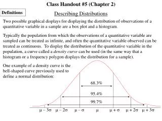
Data and Signal: Digital vs Analog Transmission
230 likes | 246 Vues
Learn about the difference between data and signal in digital and analog transmission. Explore periodic signals, electromagnetic spectrum, composite signals, digital signaling, baseband transmission, broadband transmission, channel capacity, and impairments.

Data and Signal: Digital vs Analog Transmission
E N D
Presentation Transcript
Chapter 2 and 3Handout #2 Dr. Clincy Professor of CS Lecture
Data Vs Signal • Fully explain the difference between signaland data before getting into the details (Digital Transmission) DATASIGNAL D D A (Analog Transmission) DATA SIGNAL A D A Lecture
You probably have a good idea about digital and analog signals What about analog and digital data ?? Analog data examples Voice Images Digital data examples Text Digitized voice or images Data vs Signals Lecture
Periodic Signal Characteristics If the signal’s pattern repeats over and over, we called these signals Periodic Signals Periodic Signals can be either Analog or Digital Lecture
Analog Periodic Signal Case • Amplitude (A): signal value, measured in volts • Frequency (f): repetition rate, cycles per second or Hertz • Period (T): amount of time it takes for one repetition, T=1/f • Phase (f): relative position in time, measured in degrees • General sine wave is written as • S(t) = A sin(2pft + f) Lecture
Varying S(t) = A sin(2pft + f) Lecture Note: 45 degrees because p is 180 degrees
What is Wavelength ? • The distance an electromagnetic wave can travel in the amount of time it takes to oscillate through a complete cycle • Wavelength (w) = signal velocity x period or propagation speed x period • Recall: period = 1 / frequency Another perspective of Wavelength: how far did this signal travel AS the signal goes through a FULL cycle ? Lecture
Electromagnetic Signals Electromagnetic signal can be expressed as a function of time or frequencyFunction of frequency (more important) Frequency-Domain Plot – peak amplitudes with respect to frequency Time-Domain Plot – amplitude changes with respect to time Different signals Lecture
Electromagnetic Signals - Frequency • Electromagnetic signal can be expressed as a function of time or frequency • Function of frequency (more important) • Spectrum (range of frequencies) • Bandwidth (width of the spectrum) When we talk about spectrum, we mean the range of frequencies the electromagnetic signal takes on In the example, the signal has a Frequency range of f to 3f Therefore, a electromagnetic signal can be a collection (addition) of periodic analog Signals (Composite Signal) Lecture
Composite Periodic Signal According to FOURIER ANALYSIS, a composite signal is a combination of sine waves with different amplitudes, frequencies and phases. Could converged to a square wave 3rd harmonic 9th harmonic Lecture
Electromagnetic Spectrum for Transmission Media Tell them how to study this chart Lecture
Digital Signaling • represented by square waves or pulses • Refers to transmission of electromagnetic pulses that represents 1’s and 0’s 1 cycle amplitude (volts) time (sec) frequency (hertz) = cycles per second Lecture
Digital Signal Rate • Each bit’s signal has a certain duration • Example, given a data rate of 50 kbps (or 50,000 bps) • Each would have a 0.02 microseconds duration • Duration (or bit length) = 1/50000 = .00002 sec = .02 msec Lecture
Digital Signal Sending 1 bit per level Sending 2 bits per level How many levels needed to send 5 bits at a time ???? # bits per level = log2 of (#oflevels) Lecture
Baseband Transmission • In sending the digital signal over channel without changing the digital signal to an analog signal • Use low-pass channel – meaning the bandwidth can be as low as zero • Typical: 2 computers directly connected In baseband transmission, the required bandwidth is proportional to the bit rate; if we need to send bits faster, we need more bandwidth (the frequency will need to increase) Lecture
Broadband Transmission • Broadband transmission or modulation means changing the digital signal to an analog signal for transmission • Modulation allows us to use a bandpass channel – a channel where the bandwidth doesn’t start at zero • Bandpass channels are more available than low-pass channels Lecture
Channel Capacity • As we know, impairments limits the actual data rate realized • The actual rate realized at which data can be transmitted over a given path, under given conditions is called Channel Capacity • Four concepts • Data rate – the rate, in bps, the data can be communicated • Bandwidth – constrained by the Tx and transport medium – expressed in cycles per second or Hertz • Noise – average level of noise over the communication path • Error rate – the rate in which erroneous bits are received Lecture
Impairments Lecture
Attenuation Loss of energy – the signal can lose energy as it travels and try to overcome the resistance of the medium Decibel (dB) is a unit of measure that measures a signal’s lost or gain of strength – can be expressed in power or voltage dB = 10 log10 [P2/P1] = 20 log10 [V2/V1] Samples of the power or voltage taken at times 1 and 2. Lecture
Distortion Distortion is when the signal changes its form. The each signal that makes up a composite signal could have different propagation speeds across the SAME medium – because of this, the different signals could have different delays (arriving at the receiver) – this causes a distortion. Lecture
Noise Thermal Noise - the uncontrollable or random motion of electrons in the transport medium which creates an extra signal (not sent by the transmitter) Induced Noise – undesired devices acting as a transmitting antenna and those signals being picked up Cross Talk Noise – effect of one wire crossing another wire Impulse Noise – spikes in energy (ie lightning) Lecture
Signal to Noise Ratio SNR = avg-signal-power/avg-noise-power High SNR – good (less corruption) Low SNR – bad (more noise than good power) SNR is described in Decibels (dB) SNRdB = 10 log10 SNR Lecture
Shannon Equation • Shannon’s equation is used to determine the actual capacity of a channel given noise exist • C = B log2 (1 + SNR) • B = Bandwidth • C= Channel Capacity • SNR = Signal-to-noise ratio Actual ratio Lecture