Download
1 / 44
960 likes | 2.5k Vues
Final Wall Stability in Metal Open Pit Mines Using Presplit Blasting. Kazem Oraee. Ali Mozafari. Arash Goodarzi. Nikzad Oraee-Mirzamani. Importance of presplit drilling and blasting in open pit mines.

E N D
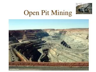
Final Wall Stability in Metal Open Pit Mines Using Presplit Blasting KazemOraee Ali Mozafari ArashGoodarzi NikzadOraee-Mirzamani
Importance of presplit drilling and blasting in open pit mines • slope stability study is one of the most considerable parameter for safety and economical factors of open pit mines. • failure of mines’ walls can potentially cause loss of lives, roads blocking, damaging to mining machinery, temporarily or permanently halt production and in the worst case scenario closing the mine. Production and Mining Benefits • Ability to maintain safe conditions in mine • Increased stability of the rock wall • Improved stripping ratios • Reduction in ore dilution • Less broken rock to load and transport • Reducing the vibration level in the rock mass • Minimizing production schedule disturbances for mine stability comparison with mechanical rock reinforcement
Failure in Pit Slop in Grasberg Gold Mine in Indonesia in 2003 The Grasberg mine is the largest gold mine in the world
Wall Failure in Pit Slop Angouran Lead & Zinc Mine in Iran 2006 25 million tons rock slide
Pit wall stability is dependent on: • geotechnical and hydrogeological issues • level of design safety (based on risk assessments) • ability to secure the ground (scaling, ground support, slope dewatering) • detrimental effects of blasting
General Principals of Control Blasting • drilling smaller diameter blasting holes along the final excavation boundary • drilling straight holes • charging with lower explosive than main holes • firing holes in sequential timescale
Controlled Blasting Methods • Line blasting • Smooth blasting • Cushion blasting • Presplit blasting
Presplit Hole Design • As a general guide for the presplit holes, spacing can be 8 to 12 times of the hole diameter or about one third to less than one half of the normal spacing used in production blast holes. It also can be determined by using the following equation: S ≤ 2 rb× 2.54 × (Pb+ T) / T • Where S = Spacing between two presplit holes (cm) • rb = Borehole radius ( cm) • Pb = Borehole pressure ( Mpa) • T = Tensile strength of rock( Mpa)
In this equation borehole detonation pressure can be calculated by: Pb = 1.69 × 10⁻³ Ye (VOD)2 (re / rb)2.6 • Where Pb= Borehole pressure in psi • Ye = Specific gravity of explosives • VOD = Detonation velocity of explosive charge ft/s • re = Radius of explosive charge in inches • rb = Radius of borehole in inches
Bore hole detonation pressure (Pa) for the full charge hole can be calculated by: Pd = × Ye × (VOD)2 × 10⁶ • Where Pd = Detonation pressure (MPa) • Ye = Density of explosive (kg/m3) • VOD = Velocity of detonation (m/s)
Buffer Holes Design(Buffer row is used to minimize blasting damage from production row to final wall) • Normally the spacing and burden of about 2/3rd of production holes are used in buffer row but if presplit and buffer rows are of same diameter then, the burdenin front of the presplit row to buffer row should be 1.5 times the presplit spacing holes and in case of different diameters, then diameter of buffer holes can be set to 12 to 15 times of presplit holes diameter. • As a general rule, when the diameters of production and buffer holes are the same, then the burden and spacing of the buffer row should be 70 to 80% of the production blast holes.
Hole Charge Distribution • Powder factors will normally range from 1.6 to 4.8 kg/m3 • The ratio of the charge diameter to hole is about 0.3 – 0.4 • The specific charge recommended for presplit holes is 0.35 to 0.5 kg/m2and generally charge factor in buffer hole is about 75% of a production hole • The charge density has to be reduced to 5 to 15 percent of the charge in production holes
Presplit Charging Methods Common charging methods in presplit holes to minimize near field blast damage Suspended charging Low density charging Continues column charging Air deck charging
Guidelines are offered by Gustafsson, 1981, DuPont Hand Book, 1977, etc. which recommends the charge loads and blast hole pattern for presplitting as shown at the below table:
Shooting the Presplit Line • In order to make a free face to reflect shock wave resulted from blasting in production holes, the presplit row must be fired at least 50ms before the main production blast. • As a rule, if the presplit holes are to be detonated with production blast holes, generally 200 to 350ms (not more) of delaying interval between presplit holes and the nearest production row or buffer row is recommended. • To achieve optimum presplit results, zero detonation delay (simultaneous blasting) to be used between presplit holes, although if the numbers of holes in presplit row are more than usual pattern, blasting may be done in separate groups with minimum delay in sequence.
Presplit Drilling & Blasting Key Points • hole spacing and charging dependent on hole size, rock strength, explosive strength and decoupling ratio • highly jointed rock requires closer hole spacing than massive rock • when firing presplit row with production row, a minimum of 200 - 350milliseconds time delay between presplit holes and nearest production holes is recommended • use zero delays between holes to achieve optimum presplit results • a bottom charge is often used to assure that the toe is pulled • straight hole drilling is a necessity
Chador Malu Iron Mine Site Profile Chador Malu iron ore mine with 400 million tons of ore reserve is the biggest iron concentrate producer in Middle East, located in 180km north-east of Yazd province in central Iran. Reconnaissance for the Chador Malu deposit was first done in 1921 and more detailed work was carried out in the beginning of 1960s. Petrography studies on the mine rocks shows that major rocks in Chador Malu mine area are Metasomatite, Albitite, Diorite, Magnetite and Hematite. The iron ore concentrate contains about 68% iron and 0.045% phosphorus.
Chador Malu drilling fleet Production & Buffer Hole Drilling: DMH, DML and DM45(Rotary system) presplit Hole Drilling: Titon 600 (DTH system) Main drill patterns: Hard Rock: Burden = 6 m & Spacing = 7 m Fractured Rock : Burden = 7m & Spacing = 8 m * ANFO explosive with Dynamite primers are used for blasting.
Chador Malu iron ore mine Drilling pattern for production holes at Chador Malu iron ore mine Drilling pattern for buffer holes at Chador Malu iron ore mine • Drilling pattern for presplit holes at Chador Malu iron ore mine
Presplit Drilling Operation presplit Holes Production Holes Buffer Holes
A schematic illustration showing drilling and blasting design in Chador Malu mine
A schematic illustration showing of drilling profile in Chador Malu mine
Drilling angles 30° 30° -Sideways: 30°/ 30°
Drilling rig position for presplit drilling at Chador Malu mine
Visual presplit evaluation • examine the presplit face and adjust spacing or charging with regard to: - smoothness of presplit surface - percent of half-casts visible - occurrence of crest failures • occurrence of plane and wedge failures in final wall
Drilling deviations in difficult condition Designed hole direction
Collaringmisalignment Collaring offset Planed hole In-hole deviation Incorrect depth Deviation due to collar error A schematic illustration showing sources of hole drilling deviations on mine bench
Conventional Drilling Methods in Surface Mines Top Hammer Down the Hole COPROD Rotary 1 3 4 2
Double Benches Drilling Using double benches presplit blasting to reduce wall failure and achieve less total drilled meters per tone
Aitik Copper Mine The Aitik copper mine is situated in Sweden. It is one of Europe's largest open pitcopper mines. Associated with the copper, large quantities of gold, silver and since 2008 molybdenum have been mined at Aitik.
Aitik Copper Mine in Sweden Mine Specification Production Started with 2 Mt/y in 1968 and now 36 Mt/y Proven Reserves : 520 Mt Grade: 0.31 % Copper ,0.2 gr/t Gold & 2.0 gr/t Silver Mine Life: 2025 Final pit depth: 400 m Production Holes: 311 mm W/O: 1:1 Pit Slope Design: 46 degree Bench height: 15 m
Presplit drilling pattern Buffer Holes 6 1/2 in Pre-split Holes 5 1/2 in Production Holes 12 ¼ in 5.0 m 10.5 m 15m 15m 16m
Typical presplit Drilling Design , Aitik Copper Mine in Sweden wall 5 ½” Pre-split holes 15 m depth 22 degree incline 4.5 m 4.5 m 5.0 m 6 ½” Bufferholes 15 m depth 6.0 m 10.5 m 12 ¼” Production holes 16 m depth 8.0 m 12 ¼” Production holes 17 m depth
Half-casts visible remained after blasting of presplit holes
Key Notes • Several techniques are used for improvement wall stability in open pit mines which among them, presplit blasting is the most pragmatic and effective approach for tackling this issue in metal open pit mines • The influence of geology can never be completely eliminated but certain measures can be taken to ensure acceptable blasting results such as selecting appropriate drill rig to control minimum drilling deviation on presplit row • DTH and COPROD drilling systems give less deviation than the other drilling methods thus they could be right choices for presplit drilling • Orientation of geological structures has the great influence on the presplit fracture, thus, survey on structural mapping and joint sets is very important to obtain the good final wall in open pit mines • Visual evaluation of presplit blasting results and modifying parameters according to mentioned table is crucial to achieve successful results.