Download
1 / 19
460 likes | 1.23k Vues
Combined Heat & Power (CHP). Group Meeting #1 January 29 th , 2013. Michael Bentel Jeremy David Erik Peterson Arpit Shah. Overview. All energy will be processed through the CHP plant Components of the CHP Plant Gas and Steam Turbine Generation of Electricity

E N D
Combined Heat & Power (CHP) Group Meeting #1 January 29th, 2013 Michael Bentel Jeremy David Erik PetersonArpit Shah
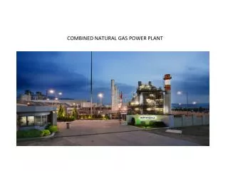
Overview • All energy will be processed through the CHP plant • Components of the CHP Plant • Gas and Steam Turbine Generation of Electricity • Boiler Production of various pressure steam (LP,MP,HP) • Natural gas from Gas Treating Plant and purge gases from Fischer Tropsch Liquids Refining Plant will be burned. • Plant water from *Team India* will be upgraded to the purity required for boiler feed water and steam turbine • CHP will provide plant and instrument air along with cooling water • All the electrical requirements will be met along with providing 50 MW electricity to the grid • Make up water will be taken from area wells, demineralized and filtered as required
Group Meeting #1 Objectives • Report Outlines Established • Conceptual Process Block Flow • Design Basis • Competing Processes • Group Meeting #2 Objectives
Outline • Design Basis √ • Block Flow Diagram √ • Process Flow Diagram • Material and Energy Balance IN PROGRESS • Calculations • Annotated Equipment List (Data Sheet) • Economic Evaluation factored from Equipment Costs • Utilities • Conceptual Control Scheme • General Arrangement – Major Equipment Layout • Distribution and End-use Issues Review • Constraints Review • Applicable Standards • Project Communications File IN PROGRESS • Information Sources and References IN PROGRESS
Proposed BFD Recycled Condensate Legend BFW = Boiler Feed Water MP = Medium Pressure LP = Low Pressure Condensate Drum Effluent Condensate Boiler Processes Water Purification BFW Plant Water Superheated Steam Electricity Steam Turbine Condensate MP steam LP steam Hot Gases Natural Gas BFW Condensate Processes Gas Turbine Processes Electricity Natural Gas Air Instrument Air Hot Return Water Cold Supply Water Dryer Compressed Air Evaporative Cooling Tower Air Processes Compressor Plant Air
Components • Turbines • Boilers • Pumps • Compressors • Evaporative Cooling Tower • Water Purification
Turbines • Two Turbine Types • Steam Turbine • Gas Turbine (i.e. Engine Turbine) • Majority of Electrical Production from Gas Turbine
Turbine - Recycle • Hot gas from Engine Turbine will be used to heat the boiler • Exhaust steam from Steam Turbine will be used as a mid & low pressure steam source • Remaining steam will be condensed and fed back to the boiler feed water
Boiler Types • Water - Tube Boiler • Fire - Tube Boiler • Fluidized Bed Combustion (FBC) • Atmospheric Fluidized Bed Combustion Boiler • Pressurized Fluidized Bed Combustion Boiler • Atmospheric Circulating Fluidized Combustion Boiler
Water-Tube Boiler • Modern boiler tube designs within 10,000-265,000 lbs/hour capacity • Produces high pressure steam • Utilization of forced and induced drafts for improved combustion efficiency • Higher thermal efficiency shifts are possible (~90%) • Less tolerance for water quality calls for water treatment plant to avoid scaling
Boiler Configuration • Water tube boilers are generally preferred in high pressure/high steam applications • High pressure steam is contained within small diameter pipes which can withstand the pressure with a thinner wall
Pumps/Compressors • Industrial grade pump necessary to circulate boiler feed water and condensate throughout the plant • Compressed air load is necessary in order to design air system
Evaporative Cooling Tower (ECT) • Provide low cost cooling below the dry bulb ambient temperature • One of the most energy efficient methods of cooling • Evaporative Cooling Towers allow a small portion of the water being cooled to evaporate into a moving air stream which will provide significant cooling to the rest of that water stream.
Water Purification • Type of purification process is dependent on types of impurities present in plant water • Boiler operation is completely dependent on the purity of incoming water • Plant water must be cooled to meet the requirements of the purification system
Types of Purification Processes • Filtration • Evaporation • Membrane Filtration + Electrodionisation Ultrapure Water
Required Information • Energy Load • Steam Load/Supply Pressure • Compressed Air Load • Recyclable Products (if applicable) • Specific Team Requirements • Plant Water Composition (Team India) • Natural Gas Production & Composition (Team Alpha) • Purge Gas and Steam Quantities (Team Foxtrot)
Future Objectives • Make final decisions on system components • Finalize CHP BFD • Probe other units for desired load requirements and waste product generation