Download
1 / 32
320 likes | 561 Vues
QoS Quality of Service. Benefits of QoS. QoS features provide improved and more predictable network service by offering the following: Dedicated bandwidth Improved loss characteristics Congestion management and Avoidance Traffic Shaping Prioritization of traffic. What makes up QoS?.

E N D
QoS Quality of Service
Benefits of QoS QoS features provide improved and more predictable network service by offering the following: • Dedicated bandwidth • Improved loss characteristics • Congestion management and Avoidance • Traffic Shaping • Prioritization of traffic
What makes up QoS? Quality of Service is managing: • Loss (packets that never get there) • Delay (packets that take too long to get there) • Jitter (variations in the arrival times of packets)
Components of QoS - Loss • Loss refers to the percentage of packets that fail to reach their destination. • Loss can result from errors in the network, corrupted frames and congested networks. With modern switched and optically based networks corrupted frames and packet losses due to network noise, interference and collisions are becoming rare. • Many of the packets lost in a healthy network are actually deliberately dropped by networking devices as a means of avoiding congestion. • For many TCP/IP based traffic flows, such as those associated with file and print services, small numbers of lost packets are of little concern. • For UDP traffic associated with real-time applications such as streaming media and voice, retransmission is not feasible and losses are less tolerable. As a guide, a highly available network should suffer less than 1% loss and for voice traffic the loss should approach 0%.
Components of QoS - Delay • Delay or Latency refers to the time it takes for a packet to travel from the source to the destination. • Delay is comprised of fixed and variable delays. • Fixed delays comprise such events as serialization and encoding/decoding. (Eg a bit takes a fixed 100ns to exit a 10Mb Ethernet interface) • Variable delays are often the result of congestion and include the time packets spend in network buffers waiting their turn to access the media. • Delay is a more significant problem for network traffic that is bi-directional in nature as the delays tend to be additive.
Components of QoS - Jitter • Delay variation or Jitter is the difference in the delay times of consecutive packets. • Jitter results in degraded audio performance. Jerky motion, loss of video quality or total loss of video depending on the encoding scheme used. • Hardware such as IP Phones use a jitter buffer to smooth out arrival times. However there are limits on a buffers ability to do this. In general, traffic that requires low latency will also require that variation in latency is also kept to a minimum. This is because any buffering used to reduce jitter will directly add to the total delay in the network. • Design rule - voice networks cannot cope with more than 30 ms of jitter.
Components of QoS - Availability • No point implementing QoS if your network is down! • Implement redundancy as well.
Quality of Service Requirements for Data Use the proven relative priority model to divide traffic into no more than four classes, such as: • Gold (Mission-Critical)Transactional, software • Silver (Guaranteed-Bandwidth)Streaming video, messaging, intranet • Bronze (Best-Effort and Default class)Internet browsing, E-Mail • Less-than-Best-Effort (Optional; higher-drop preferences)FTP, backups, applications (Napster, KaZaa)
Quality of Service Requirements for Voice Voice traffic should be given: • Loss should be no more than 1%. • One-way latency should be no more than 150-200 ms. • Average jitter should be no more than 30 ms. • 21-106 kbps of guaranteed priority bandwidth is required per call (depending on the sampling rate, codec and Layer 2 overhead). • 150 bps (+ Layer 2 overhead) per phone of guaranteed bandwidth is required for Voice Control traffic.
Quality of Service Requirements for Video Requirements vary: • Video conferencing requirements are similar to voice. • Streaming media is often buffered for several seconds so latency requirements can be relaxed. • Allow for video’s bursty nature…
Quality of Service Mechanisms QoS Service Models: • Best EffortThe default if no explicit QoS is configured • Integrated Services Model – IntServRSVP – A pre-negotiated QoS path is established end-to-end.Not well established as the application software must do the negotiating. • Differentiated Services Model – DiffServEach hop (router) prioritises traffic according to configuration.Sometimes referred to as a per-hop-behaviour. • DiffServ is the focus of this course
Establishing Differentiated Services There is a need to “tag” traffic with a QoS level so that a specific per-hop treatment can be applied: • Layer 2 – CoS – Class of Service field. • 3 bits 0-7 value • Field is present in ISL and 802.1Q/P encapsulations • Layer 3 – ToS – Type of Service field. • 3 bits 0-7 value Only relevant to IP • Often referred to as “IP Precedence” • Layer 3 – DSCP – Differentiated Services Code Point • Supersedes ToS • 6 bits (first 3 bits are ToS) 0-63 value 0 is the lowest priority
Establishing Differentiated Services It may seem confusing to have three options for marking traffic: • The way to proceed is often determined by the QoS capabilities of hosts, switches and routers within the network. • In many instances it may be necessary to use different marking techniques at different points within a network. • For example, it is common to use the DSCP to mark the QoS requirements of packets through the routed layers of the network and mark the frames using the CoS to allow layer 2 devices such as switches to provide for the QoS requirements of packet at the data link layer.
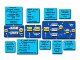
Modular QoS Command Line InterfaceMQC The Modular QoS Command Line Interface or MQC is central to Cisco’s model for implementing IOS based QoS solutions. The MQC breaks down the tasks associated with QoS into modules that: • Identify traffic flows • Classify traffic flows as belonging to a common class of QoS. • Apply QoS policies to that class • Define the interfaces on which the policy should be enforced.
MQC Classification of trafficThe class-map • The class map is used to associate one of several attributes with a QoS treatment that should be given to that traffic. • The attributes available vary depending on the hardware platform. Example: Switch(config)# class-map match-any criticalSwitch(config-cmap)# match interface fastethernet 0/1 Any traffic coming in on fa0/1 will be classed as “critical”. In the next slide we define what to do with “critical” traffic.
MQC - Defining the QoS PolicyThe policy-map The policy-map command is used to create a traffic policy. The purpose of a traffic policy is to configure the QoS features that should be associated with the traffic that has been classified in a user-specified traffic class. A traffic policy contains three elements: • Policy Name • Traffic class (specified with the class command) • QoS policies to be applied to each class Eg. • Switch(config)# policy-map policy1 • Switch(config-pmap)# class critical • Switch(config-pmap-c)# bandwidth 3000 A bandwidth total of 3000 kbps will be given to the traffic classified as “critical” by the class-map in the previous slide.
MQC - Applying the policy to an interface The service-policy Just like an Access List, you must apply a service-policy to a particular interface and specify it as applying to input or output traffic. • Switch(config)# interface fastethernet 0/1 • Switch(config-if)# service-policy output policy1 • Switch(config-if)# exit
MQC – Using QoS in real networks When classifying traffic, several common situations arise: • Downstream hardware has already set the QoS field at layer 2 or 3. For example an IP phone can set CoS. • You can choose to “trust” the device and copy the ToS/CoS. • You can re-write the CoS to a new value • Perhaps trust an IP phone but not the CoS/ToS from a PC… • Downstream device has not set any QoS field. • You can assign traffic with a default QoS value. • At the edge of the network (Access layer, and links to other autonomous systems) it is common to not trust CoS/ToS values. Rather you would use ACL’s to define the QoS requirements and write an appropriate CoS/Tos Value • In the core of your network it is likely that you will trust the CoS/ToS that you assigned at the edge.
Winners and Losers In order to give priority QoS to one class of traffic, another (lower) class of traffic must suffer. • Policing – Involves either marking down the DSCP value for packets that are exceeding the bandwidth allocation (non conforming) or dropping the packet. • Policing uses a “Token Bucket” todetermine non conformance. • Rate and burst-sizeare configurable • CAR – Committed AccessRate – Similar to FrameRelay’s CIR
Scheduling Scheduling is used to give different queueing priorities according to the packet or frames DSCP or CoS value. • First In First Out – FIFO (No QoS treatment) • Weighted Fair Queuing - WFQ • Class Based Weighted Fair Queuing - CBWFQ
Weighted Fair Queuing (WFQ) WFQ Services queues with a higher ToS more frequently than those with a lower ToS Traffic Destined for Interface Transmit Queue Output Line Classify Weighted Fair Scheduling Configurable Number of Queues • Flow-Based Classification by: • Source and destination address • Protocol • Session identifier (port/socket) Interface Buffer Resources • Weight Determined by: • Requested QoS (IP Procedure, RSVP) • Frame Relay FECN, BECN, DE(For FR Traffic) • Flow throughput (weighted-fair)
Congestion Avoidance Prioritising traffic in a congested network is fine but it would be better to avoid the congestion altogether. • Congestion leads to dropped packets. By default packets are dropped indiscriminately once a router’s buffers are full. This is known as “tail drop”. • Dropping packets causes TCP to reduce its window-size thus reducing the data rate and lessening congestion – good! • Tail drop causes many TCP sessions to do this simultaneously – bad! • This means that bandwidth may not be fully utilised and it results in a traffic flow that resembles a “saw tooth”. • Tail drop can result in bursty traffic flows that cause other problems such as jitter.
Congestion AvoidanceWeighted Random Early Detection - WRED RED drops packets randomly when a routers buffer fills beyond a certain threshold. This random dropping prevents the problems associated with tail-drop. No actual data loss occurs because TCP retransmits. WRED takes this one step further and facters in QoS parameters when it “randomly” drops a packet. WRED drops packets according to the following criteria: • RSVP flows are given precedence over non-RSVP flows, to ensure that time-critical packets are transmitted as required. • The IP precedence or DSCP value of the packets. Packets with higher precedence are less likely to be dropped. You can control how WRED determines when and how often to drop packets based on precedence value if you are not satisfied with the default settings. • The amount of bandwidth used by the traffic flow. Flows that use the most bandwidth are more likely to have packets dropped. • The weight factor you have defined for the interface determines how frequently packets are dropped.
Traffic Shaping • Designed to smooth traffic flows by limiting instantaneous bandwidth. • Cisco IOS QoS software has three types of traffic shaping: • Generic Traffic Shaping (GTS) • Class-based (CAR) • Frame Relay Traffic Shaping (FRTS) • All three traffic shaping methods are similar in implementation, though their CLIs differ somewhat and they use different types of queues to contain and shape traffic that is deferred. In particular the token bucket is employed by all schemes.
QoS over low speed links • The limited bandwidth of a low speed WAN link creates particular challenges on QoS. • Prioritisation of delay sensitive traffic becomes critical. • Sometimes waiting for just one packet is too long!
QoS over low speed links • Examine the table below. It outlines the time taken for various sized packets to be sent over different bandwidth WAN links. • If we have a 64kbps ISDN link and our voice packet is in the queue behind a 1500 byte FTP packet we have a problem because the maximum latency for voice is around 200mS. This doesn’t give us much to play with if there are several more WAN hops for our voice packet to traverse.
Link Fragmentation and Interleaving LFI • The solution is to use LFI to cut-up the larger packets so that the priority packets can be interleaved with fragments of larger packets. • You can specify the maximum amount of time in milliseconds that each fragment can take. This will determine the size of the fragment • LFI uses PPP to handle the reassembly
Compressed Real-Time Transport Protocol • RTP is the Internet-standard protocol for the transport of real-time data, including audio and video. • Compressed Real-Time Transport Protocol, or CRTP, is used on a link-by-link basis to compress the IP/UDP/RTP header. In a packet voice environment when framing speech samples every 20 milliseconds; this scenario generates a payload of 20 bytes. The total packet size comprises an IP header (20 bytes), a UDP header (8 bytes), and an RTP header (12 bytes) combined with a payload of 20 bytes. • It is evident that the size of the header is twice the size of the payload. When generating packets every 20 milliseconds on a slow link, the header consumes a large portion of the bandwidth. To avoid the unnecessary consumption of available bandwidth, CRTP is used on a link-by-link basis. • This compression scheme reduces the IP/UDP/RTP header to 2 bytes most of the time when no UDP checksums are being sent or 4 bytes when UDP checksums are used. • Note: Cisco only recommends using cRTP with links lower than 768 Kbps, unless the router is running at a low CPU utilization rate. Monitor the router's CPU utilization and disable cRTP if it's above 75%.