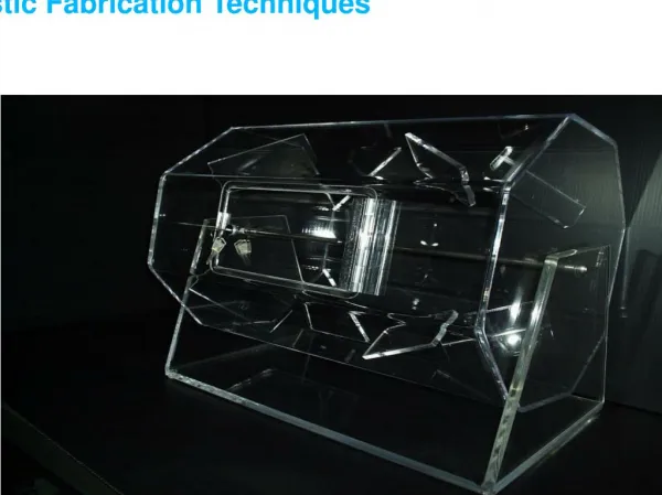
Structure fabrication techniques and possibilities
Structure fabrication techniques and possibilities. M.Taborelli. Disk structures Quadrant structures ….most of it inspired by 30GHz tests and experience. disk structures. Copper, disk structures. - Machining by diamond turning : shape accuracy of 2-3 m m in the iris region

Structure fabrication techniques and possibilities
E N D
Presentation Transcript
Structure fabrication techniques and possibilities M.Taborelli Disk structures Quadrant structures ….most of it inspired by 30GHz tests and experience M.Taborelli, TS-MME
disk structures Copper, disk structures - Machining by diamond turning: shape accuracy of 2-3 mm in the iris region -alignment of the disks on V-shaped marble before assembly in a stack: use external “cylinder” surface as reference. -assembly by vacuum brazing or by bolting -achieved accuracy? - No rf-damping M.Taborelli, TS-MME
disk structures Recrystallization after thermal treatment (vacuum brazing cycle at 820 C) 30 GHz copper structures: surface quality Ra = 0.05 mm M.Taborelli, TS-MME
disk structures Disk structures: other materials and configuration for bimetal • -Diamond turing with insert. Successfully tested with Mo and • W irises (single iris or full structure) • Insert of complete iris in new material or bi-metal (for iris tip only) • Assembly by clamping (bolting) only, because of the difference in thermal expansion; potential problem for proper electrical contact (oserved copper transfer on refractory metal) Iris insert M.Taborelli, TS-MME
disk structures Copper disks with damping (SLAC design) • Turning is no longer sufficient, milling is necessary to produce the radial slits • Full 3D milling is needed to avoid steps and burrs M.Taborelli, TS-MME
E Why +/- 1 microns precision? 0. Frequency matching (about 4MHz deviation per mm on cavity radius at 30 GHz), or tuning 1. Longitudinal alignment precision : <5 mm alignment error of the irises induces transversal kick on the beam ; this effect is independent of frequency (11 or 30 GHz) if we keep similar iris aperture “bookshelfing” error from cell to cell 2. RF – to-beam phase: better than 0.10 ( some microns on cavity shape) to preserve efficiency and beam stability 3.Avoid steps and kinks on the surfaces (field enhancement b) 4. Ra should be around ¼ of the skin depth to preserve electrical conductivity M.Taborelli, TS-MME
quadrant structures 53 mm Copper quadrant structures: example 30GHz • machining by 3D milling (carbide tools) • -alignment of the quadrants by balls and gooves (plastic deformation of copper): possible improvement? • -assembly by brazing or by bolting • -achieved accuracy? Grooves are positioned at some 6 mm accuracy • -damping implemented in the design 160 mm M.Taborelli, TS-MME
Tolerances: 5 mm shape tolerance M.Taborelli, TS-MME
quadrant structures Metrology on copper quadrants Measurement: coordinate measuring machine, contact with 0.1N force, accuracy +/-3 µm (at CERN), scan pt. by pt. on the surface ………in parallel with RF low power control M.Taborelli, TS-MME
quadrant structures Achieved shape accuracy Surface finishing on copper, Ra=0.1-0.4 mm M.Taborelli, TS-MME
quadrant structures Possible sources of the error in 3D milling • Error on tool diameter, tool length, tool run-out : dynamic dimensions • Error on tool shape • Tool flexure (larger tools at 11GHz should be favourable) • Tool consumption during machining • Thermal expansion of the piece...probably not relevant for the present short prototypes • Temperature stability, dynamics of the machine tool • Positioning accuracy of the machine tool (machine tool with higher nominal accuracy give better surface finish) M.Taborelli, TS-MME
quadrant structures milling, best result Diamond turning, disks Surface quality: on copper HDS60 milling milling M.Taborelli, TS-MME
quadrant structures Other materials and bi-metal Full structure in single material for rf testing Joining Mo to CuZr C15000 alloy by diffusion bonding through HIP or explosion bonding; tested by machining, shear and pull strength test Cu, Mo, Al, StSt, Ti HIP diffusion bonding Explosion bonding M.Taborelli, TS-MME
quadrant structures 1cm 100 mm Other machining techniques: • -3D milling of copper with single crystal diamond tool? • Elliptical vibration milling of copper? • Electrochemical machining sufficiently accurate? • Electro discharge machining of refractory metals • ( micro-cracks on molybdenum), development in progress Ecole d’ingenieurs Geneva M.Taborelli, TS-MME
quadrant structures Metrology problems Requires high accuracy, ideally 0.1 mm to control at 1 mm level Force of the sensor should be low (0.1 N leaves marks) Available optical methods are not adapted for complex 3D shapes Trace of sensor contact HDS11-Aluminium M.Taborelli, TS-MME
Production of structures RF design of structures RF Model Mech. design, fabrication, preparation R&D Materials, preparation Test, analysis SLAC KEK CTF3 The goal is the fabrication of 1 geometry in 4 months and 10 geometries per year M.Taborelli, TS-MME
Present production situation Available Under production Under mech. Design. Under RF design M.Taborelli, TS-MME
Thank you M.Taborelli, TS-MME
HDS11-small-Mo HDS60 M.Taborelli, TS-MME