MSA - ALTAIR 4X Gas Meter
210 likes | 783 Vues
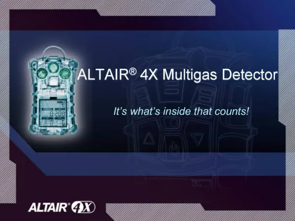
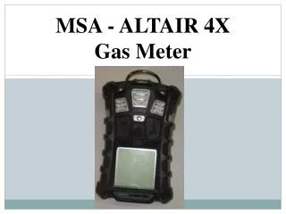
MSA - ALTAIR 4X Gas Meter. Instrument Overview. 1 – MSA “Link” Communicator 2 – Self LED (green) and Fault LED (yellow) 3 – Sensor Inlet 4 – Horn 5 - Button 6 - Button 7 - Button 8 – Display 9 – Alarm LEDs (4). Instrument Overview. 10 – Clip

MSA - ALTAIR 4X Gas Meter
E N D
Presentation Transcript
Instrument Overview 1 – MSA “Link” Communicator 2 – Self LED (green) and Fault LED (yellow) 3 – Sensor Inlet 4 – Horn 5 - Button 6 - Button 7 - Button 8 – Display 9 – Alarm LEDs (4)
Instrument Overview 10 – Clip 11 – Charging Connection 12 – Screws (4) 13 – Charge LED (red/green) LED Descriptions Green – flashes every 15 seconds unit is on and operating Red – Alarm condition Yellow – fault condition Red/Green – charging status Red – is charging Green – charge complete
On-Screen Indicators By row starting at the top left. 4-no gas cylinder applied – expose to fresh air 5-indicates “Peak” reading or high alarm 6-indicates STEL alarm 7-hourglass indicates user should wait 8-battery condition 9-cal gas must be applied 10-indicated minimum value or low alarm 11-indicates TWA alarm 12-indicates required interaction 13-indicates “Motion Alert” is active 14-Heart indicates sensor life warning 15-check mark indicates successful bump or calibration 16-Sensor Labels 1 – Graphic Symbols 2 – Gas Types 3 – Gas Concentration 4 5 6 7 8 9 10 11 12 13 14
Battery Life Indicator The battery condition icon continuously displays in the upper right-hand corner of the display. As the battery is depleted, the battery icon segments blank until only the battery icon outline remains. Warning If the battery warning alarm activates while using the instrument, leave the area immediately as the end of the battery life is approaching. The alarm indicates the there is 30 minutes of operating time left. Normal run time for the unit is 24 hours.
Operation of Unit • Turn “ON” in fresh air for the “Fresh Air Setup.” • The instrument does a self test and then goes into “Fresh Air Setup” • All display segments are activated • Audible alarm sounds. • Alarm LED lights • Vibrating alarm activates.
Operation of Unit After the instrument does its self check it will display FAS? Asking if a fresh air sample is to be done. Press enter. If you forget to zero the meter it will revert to its last fresh air setup. The “Fresh Air Setup” (FAS) is for automatic ZERO calibration of the instrument. The FAS has limits. The zero of any sensor that is outside of these limits will not be adjusted by the FAS command.
Operation of Unit WARNING Do NOTactivate the Fresh Air Setup unless you are certain you are in fresh air, uncontaminated; otherwise, inaccurate readings can occur which can falsely indicate that a hazardous atmosphere is safe.
Operation of Unit Measurement Mode • The meter has preset measures for all four gases to alert you when the concentration has become dangerous. • The combustible gas measures the % of the lower explosive limit of 5. Meaning when the meter reaches 100% it is at its LEL. When this is reached the meter will alarm and flash XXX.
Maintenance Wash with a cloth of mild soap and water Make a note on the board if -there is an issue with a meter -the meter needs bump tested/calibrated -the meter needs charged