Nanoscale Science and Technology II. Tools and Processing Techniques
360 likes | 519 Vues
Nanoscale Science and Technology II. Tools and Processing Techniques. M. Meyyappan Director, Center for Nanotechnology NASA Ames Research Center Moffett Field, CA 94035 email: meyya@orbit.arc.nasa.gov web: http://www.ipt.arc.nasa.gov Guest Lecturer: Dr. Geetha Dholakia

Nanoscale Science and Technology II. Tools and Processing Techniques
E N D
Presentation Transcript
Nanoscale Science and Technology II. Tools and Processing Techniques M. Meyyappan Director, Center for Nanotechnology NASA Ames Research Center Moffett Field, CA 94035 email: meyya@orbit.arc.nasa.gov web: http://www.ipt.arc.nasa.gov Guest Lecturer: Dr. Geetha Dholakia Nanoscale Imaging Tools
Overview of microscopy • Optical Microscope • Electron Microscopes Transmission electron microscope Scanning electron microscope • Scanning probe microscopes Scanning tunneling microscope Atomic force microscope NOTE: This talk has been put together from material available in books, various websites, and from data obtained by NASA nanotech group. I have given acknowledgements where ever possible.
OPTICAL MICROSCOPES Image construction for a simple biconvex lens
Important parameters • Magnification: Image size/Object size • Resolution: Minimum distance between two objects that can still be distinguished by the microscope.
Total visual magnification MOBJ X MEYE Schematic of a simple optical microscope www.microscopy.fsu.edu
Rayleigh criterion for resolutionΔx ~ 0.2μ www.microscopy.fsu.edu ; www.imb-jena.de Please check the first web site to watch a Java Applet on the dependence of Rayleigh criterion on of incident radiation and on the numerical aperture.
THE ELECTRON MICROSCOPES de Broglie : λ = h / mv λ: wavelength associated with the particle h: Plank’s constant 6.63 10^-34 J.s; mv: momentum of the particle m_e: 9.1 10^-31 kg; e 1.6 10^-19 coloumb P.E eV = mv2/2 => λ = 12.3/VÅ V of 60kV, λ= 0.05 Å => Δx ~ 2.5 Å Microscopes using electrons as illuminating radiation TEM & SEM
Components of the TEM • Electron Gun: Filament, Anode/Cathode • Condenser lens system and its apertures • Specimen chamber • Objective lens and apertures • Projective lens system and apertures • Correctional facilities (Chromatic, Spherical, Astigmatism) • Desk consol with CRTs and camera Transformers: 20-100 kV; Vacuum pumps: 10-6 – 10-10 Torr
Schematic of E Gun & EM lens Magnification: 10,000 – 100,000; Resolution: 1 nm-0.2 nm www.udel.edu
TEM IMAGES www.udel.edu ; www.nano-lab. com ; www.thermo.com
Schematic of SEM Physics dept, Chalmers university teaching material
Electron scattering from specimen www.unl.edu • Resolution depends on spot size • Typically a few nanometers • Topographic scan range: order of mm X mm • X rays: elemental analysis
Some SEM images CNT in an array Blood platelet Dia: 7 CNT: NASA nanotech group; Blood cell: www. uq.edu. au
Scanning probe microscopy • 1982 Binning & Rohrer, IBM Zurich. • STM, AFM & Family. • Resolution: Height: 0.01nm, XY: 0.1nm • Local tip-sample interaction: Tunneling (electronic structure), Van der Waal’s force, Electric/Magnetic fields. • Advantages: atomic resolution, non destructive imaging, UHV, ambient/liquids, temperatures. • Diverse fields: materials science, biology, chemistry, tribology. www.spm.phy.bris.ac.uk
Scanning tunneling microscope I e-2d I: Tunneling current; (decay const.) = 2m/ h d: tip-sample distance www.mpi-halle.mpg.de ; spm.aif.ncsu.edu
Topography (conducting surfaces and biological samples). ST Spectroscopy (from IV obtain the DOS). STP(spatial variation of potential in a current carrying film). BEEM (Interfacial properties, Schottky barriers). Vibration isolation: 0.001nm Reliable tip - sample positioning Electrical and acoustic noise isolation Stability against thermal drift Good tips STM Mechanical stability Operational modes and requirements
Electronics • Current to voltage converter: Gain 108-1010 • Bias Circuit • Feedback Electronics: Error amplifier, PID controller, few filters. • Scan Electronics: +X -X +Y -Y ramp signals (generated by the DA card). • HV Circuit amplifies the scan voltages and the feedback signal to ± 100 V from ± 10 V. • Data acquisition and image display
STM Images HOPG: ambient Physics dept, IISc, India Si(7X7): UHV Courtesy: RHK Tech.
More pictures • 2.6 nm X 2.6 nm self assembled organic film. Molecular resolution. NASA nano group • Quantum corral Fe on Cu(111) Courtesy: Eigler, IBM Almaden
Scanning tunneling spectroscopy • dI/dV DOS of sample • J.C. Davis Group, Berkeley. • Effect of Zn impurity on a high Tc superconductor • T: 250mK.
Scanning tunneling potentiometry Platinum film Physics dept, IISc, India
ATOMIC FORCE MICROSCOPE www.fys.kuleuven.ac.be ; www.chem.sci.gu.edu.au
AFM modes of operation • Contact mode Force: nano newtons • Non-contact mode Force: femto newtons Freq. of oscillation 100kHz • Intermittent contact • Image any type of sample. Park Scientific handbook
AFM Images Mica: digital instruments; Grating: www.eng.yale.edu
Acronyms galore! • MFM: Magnetic force microscopy • EFM: Electrostatic force microscopy • TSM: Thermal scanning microscopy • NSOM: Near field scanning optical microscope
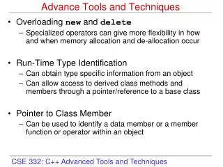
Top-Down vs. Bottom-Up Techniques • Top-down techniques take a bulk material, machine it, modify it into the desired shape and product - classic example is manufacturing of integrated circuits using a sequence of steps sush as crystal growth, lithography, deposition, etching, CMP, ion implantation… (Fundamentals of Microfabrication: The Science of Miniaturization, Marc J. Madou, CRC Press, 2002) • Bottom-up techniques build something from basic materials - assembling from the atoms/molecules up - not completely proven in manufacturing yet Examples: Self-assembly Sol-gel technology Deposition (old but is used to obtain nanotubes, nanowires, nanoscale films…) Manipulators (AFM, STM,….) 3-D printers (http://web.mit.edu/tdp/www)
Deposition Techniques Inorganic Materials Organic Materials • Physical • Chemical (CVD) • Plasma deposition • Molecular beam epitaxy (can be physical or chemical) • Laser ablation • Sol-gel processing Thermal evaporation • Spin coating • Dip coating • Self-assembling monolayers Sputtering
Physical Deposition Approaches • Thermal evaporation - Old technique for thin film dep. - Sublimation of a heated material onto a substrate in a vacuum chamber - Molecular flux = N0 exp = activation energy - heat sources for evaporation (resistance, e-beam, rf, laser) • Sputtering - The material to be deposited is in the form of a disk (target) - The target, biased negatively, is bombarded by positive ions (inert gas ions such as Ar+) in a high vacuum chamber - The ejected target atoms are directed toward the substrate where they are deposited.
Sol-gel Technology • Versatile process for making ceramic and glass materials (powders, coatings, fibers… variety of forms). • Involves converting from a liquid ‘solution’ to a solid ‘gel’ • Start with inorganic metal salts or metal alkoxides (called precursors); series of hydrolysis and polymerization reactions to prepare a colloidal suspension (sol). • Next step involves an effort to get the desirable form - thin film by spin or dip coating - casting into a mold • Further drying/heat treatment, wet gel is converted into desirable final product • Aerogel: highly porous, low density material obtained by removing the liquid in a wet gel under supercritical conditions
Sol-gel Technology (cont.) • Ceramic fibers can be drawn from the gel by adjusting the viscosity • Powders can be made by precipitation, or spray pyrolysis • Examples - Piezoelectric materials such as lead-zircomium-titanate (PZT) - Thick films consisting of nano TiO2 particles for solar cells - Optical fibers - Anti-reflection coatings (automotive) - Aerogels as filler layer to replace air in double-pane structures
3D Printing • Check http://www.mit.edu/tdp/www • Solid freeform fabrication, currently working only at sub-mm level, is amenable for nanoscale prototyping • Works by building parts in layers. Starts with a CAD model for the structure • Each layer begins with a thin distribution of powder spread over the surface of a powder bed • Technology similar to ink-jet printing • A binder material selectively joins particles where the object formation is desired • A piston is lowered that leads to spreading the next layer • Layer-by-layer process is repeated • Final heat treatment removes unbound powder • Allows control of composition, microstructure, surface structure