Download
1 / 50
540 likes | 777 Vues
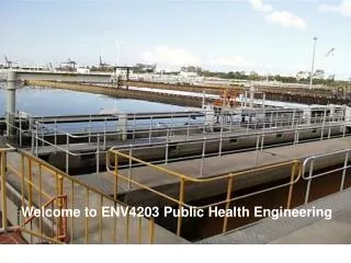
Welcome to ENV4203 Public Health Engineering. ENV4203 PUBLIC HEALTH ENGINEERING What are the roles of the practitioner?. Urban drainage & flood protection (module 1) Source, storage & transmission of water (module 2) Water treatment to meet standards (modules 4, 5)

E N D
ENV4203 PUBLIC HEALTH ENGINEERINGWhat are the roles of the practitioner? • Urban drainage & flood protection(module 1) • Source, storage & transmission of water(module 2) • Water treatment to meet standards(modules 4, 5) • Distribution of water to consumers(module 3) • Collection of wastewater, treatment & disposal(modules 6 - 9) • Collection & disposal of MSW(module 10) • Air & noise pollution abatement Module 1
URBAN STORMWATER DRAINAGEOn completion of this module you should be able to: • Discuss the concepts of minor and major drainage design • Use the Rational Method • Plan and design an urban stormwater drainage system Module 1
STORMWATER DRAINAGE PLAN Module 1
URBAN STORMWATER DRAINAGESome important features • Drainage is fundamental to urban living • Low individual costs but high aggregate costs • Structures are low profile and usually out of sight • Flooding occurs when the design fails Module 1
URBAN STORMWATER DRAINAGESome important concepts • Minor drainagedesign caters for the frequent storm events and involves structures such as kerb gutter, inlet pits and pipe system • Frequent storms have low intensity values • Major drainagedesign caters for infrequent, low probability storms of high intensity values and flows are channelled into roadways, natural channels and detention basins Module 1
URBAN STORMWATER DRAINAGEMinor and major drainage design Module 1
URBAN STORMWATER DRAINAGEGoals of urban drainage • Collect and safely convey stormwater to receiving waters • To flood proof important buildings/areas (major drainage design) • To cater for the frequent or nuisance stormwater flows (minor drainage design) • To retain within each catchment as much incident rain as possible Module 1
URBAN STORMWATER DRAINAGEDesign of urban stormwater drainage involves • Hydrologic calculations of catchment flow rates • Hydraulic calculations of pit energy and friction losses, and pipe sizes Module 1
URBAN STORMWATER DRAINAGERational Method equation (hydrologic) • Assumes a relationship between duration of rainfall required to produce peak flow and the longest travel time of the catchment • Peak flow occurs when duration of storm equals the time of concentration • Q = F C A I Module 1
URBAN STORMWATER DRAINAGERational Method equation (continue) • Surface hydrologic flow is based on the longest travel time for the catchment • Pipe hydrologic flow is based on the longest cumulative travel time including pipe flow time for the corresponding cumulative upstream catchment Module 1
URBAN STORMWATER DRAINAGETime of concentration, tc • The runoff travel time from the most remote point of the catchment to the outlet • Or the time taken from the start of the rainfall until the whole catchment is simultaneously contributing to flow at the outlet • It comprises the travel time from roof gutters, open ground, kerb gutter, pipes and channels Module 1
URBAN STORMWATER DRAINAGEComponents of surface & pipe travel times • Overland/allotment travel time from kinematic wave equation • Gutter travel time from Izzard’s equation • Pipe travel time i.e. length/velocity Module 1
URBAN STORMWATER DRAINAGEOverland/allotment travel time • Use kinematic wave equation • t = 6.94 (L. n*)0.6 /(S0.3I0.4) • tI0.4 = 6.94 (L. n*)0.6 /(S0.3) • Select t corresponding to tI0.4 from prepared table Module 1
URBAN STORMWATER DRAINAGEGutter travel time • Use Izzard’s equation • Q = 0.375 F.[(Zg/ng).(dg8/3 - dp8/3) + (Zp/np).(dp8/3 - dc8/3)].So1/2 Module 1
URBAN STORMWATER DRAINAGEAverage Recurrence Interval (ARI), Y • The average period between years in which a value (rainfall or runoff) is exceeded • It is not the time between exceedances of a given value • Periods between exceedances are random Module 1
URBAN STORMWATER DRAINAGERainfall intensity, I, is dependent on • Locality of the catchment • Recurrence interval used in the design • Time of concentration or duration of storm Module 1
URBAN STORMWATER DRAINAGEPreparation of the Intensity-Frequency-Duration (IFD) data for any location in Australia from • 6 master charts of log normal design rainfall isopleths • 1 regionalised skewness map • 2 charts of geographical factors to determine short duration intensities Module 1
URBAN STORMWATER DRAINAGEPreparation of the Intensity-Frequency-Duration (IFD) data for any location in Australia to produce • Standard ARIs of 1, 2, 5, 10, 20, 50 and 100 years • Standard durations of 5, 6, 10, 20, 30 minutes, 1, 2, 3, 6, 12, 24, 48, and 72 hours Module 1
Intensity-Frequency-Duration chart Module 1
Required steps for IFD preparation Step 1 Determine input data Module 1
Required steps for IFD preparation Step 2 Intensities for durations less than 1 hour • Calculate the 6 min intensities for 2 and 50 years ARI • 2I6m = F2 x (2I1)0.9equation A(3.1) • 50I6m = F50 x (50I1)0.6equation A(3.2) Module 1
Required steps for IFD preparation Step 3 LP III rainfalls for 2 & 50 years for basic durations • Calculate the mean and standard deviations of the log of the rainfall intensities for the specific durations • XD = log10 (2ID/1.13) equation A(3.3) • SD = 0.4869 x log10(50ID x 1.13/2ID) equation A(3.4) • YID =YP [antilog10(XD + YK x SD)] equation A(3.5) • YK = 2[{(YKN – G/6) x G/6 + 1}3 – 1]/G equation A(3.6) Module 1
Required steps for IFD preparation Step 4 Plot LP III for 2 & 50 years and basic durations • This step is optional for the algebraic method • However, it is recommended as a graphical confirmation of your calculations Module 1
Required steps for IFD preparation Step 5 Determine LP III rainfalls for 5, 10, 20 & 100 years and for basic durations 6 m, 1, 12, 72 h • Calculate the mean and standard deviations of the log of the rainfall intensities for the basic durations • XD = log10 (2ID/1.13) equation A(3.3) • SD = 0.4869 x log10(50ID x 1.13/2ID) equation A(3.4) • YID =YP [antilog10(XD + YK x SD)] equation A(3.5) • YK = 2[{(YKN – G/6) x G/6 + 1}3 – 1]/G equation A(3.6) Module 1
Required steps for IFD preparation Step 6 Calculate 1 ARI intensities for basic durations • Calculate the 1 year ARI intensities for basic durations D = 6 min, 1, 12, and 72 h • 1ID = 0.885 x 2ID/[1 + 0.4046 log10(1.13 x 50ID/2ID)]) eqn A(3.7) Module 1
Required steps for IFD preparation Step 7 Interpolate from basic durations to all other durations for all ARIs • Use equationsA(3.8), A(3.9) and A(3.10) • Refer also to Table A1 in the appendix of Reading 1.1 • Step 8 smoothing of the IFD curves via a 6th degree polynomial is not required Module 1
URBAN STORMWATER DRAINAGERunoff Coefficient, C • Ratio of runoff to rainfall frequency curves • Based on the 10 I1 storm intensity • Runoff coefficient is related to the fraction impervious of the catchment Module 1
URBAN STORMWATER DRAINAGERunoff Coefficient, C • Based on 10I1 rainfall intensity • C’10 = 0.1 + 0.0133 (10I1 - 25) • C10 = 0.9 f + C’10 (1 - f) • CY = FY C10 Module 1
Runoff coefficients C’10 = 0.1 + 0.0133(10I1 - 25) C10 = 0.9f + C’10 (1 – f) Module 1
URBAN STORMWATER DRAINAGEHydrologic Flow • Q = F (C A) I m3/s • C = runoff coefficient • A = catchment area, ha • I = rainfall intensity, mm/h • F = proportionality constant i.e. 1/360 Module 1
Rational Method The time of concentration is 20 min When does peak flow occur? Let us examine 4 rainfall events • Rainfall (1) 10I60 = 25 mm/h • Rainfall (2) 10I25 = 42 mm/h • Rainfall (3) 10I20 = 48 mm/h • Rainfall (4) 10I15 = 55 mm/h Module 1
Rational Method Using the Rational Method equation for each rainfall event The 4 contributing flows are • Q(1) = 0.1 x 25/0.360 = 6.94 L/s • Q(2) = 0.1 x 42/0.360 = 11.67 L/s • Q(3) = 0.1 x 48/0.360 = 13.33 L/s • Q(4) = 0.1 x (15/20) x 55/0.360 = 11.46 L/s Module 1
Rational Method (non-homogenous catchment) The longest time of concentration is 60 min, and corresponding 10I60 = 25 mm/h SCA = 1 x 0.1 + 0.4 x 0.20 = 0.18 ha Q = F CA I = 0.18 x 25/0.36 = 12.5 L/s Note the anomaly that the runoff is less than for the single impervious 0.1 ha catchment of 13.33 L/s Module 1
Rational Method (non-homogenous catchment) The partial area effect uses time of concentration of 20 min for the impervious area, and corresponding 10I20 = 48 mm/h SCA = 1 x 0.1 + 0.4 x 0.20 x 20/60 = 0.127 ha Q = F CA I = 0.127 x 48/0.36 = 16.93 L/s Note the partial area effect resulted in a higher flow than the full area design Module 1
URBAN STORMWATER DRAINAGEPit Entry Capacity • Design forperformance and safety • Grate and kerb inlets • Use standard design based on local authority requirements • On-grade and sag pits Module 1
URBAN STORMWATER DRAINAGERational Method has some inconsistencies • Rainfall intensity is assumed uniform (temporal and spatial) • Antecedent catchment condition is not recognised • Partial area effects may result in larger flows Module 1
URBAN STORMWATER DRAINAGEHydraulic Design • Simplest design is open channel flow • Adopted design is full-flow under pressure or surcharge where water rises within pits but do not overflow on to streets • This allows greater freedom is selecting pipe slopes, improved prediction of hydraulic behaviour and consistency in design Module 1
URBAN STORMWATER DRAINAGEHydraulic Design (continue) • Friction slope Pipe slope • Allow 150 mm freeboard for USWL & DSWL • USWL - DSWL Losses • Losses = Friction + Pit energy losses • Calculate pipe size to satisfy above condition Module 1
URBAN STORMWATER DRAINAGEHydraulic Design (continue) • Limiting downstream condition may be pipe invert level or flood level • Carry out hydraulic check from downstream limiting condition and work upwards • Ensure no overflow at gully pits • Good practice to include horizontal profile Module 1
Hydraulic Design Proforma * Lower of [7] – freeboard or lowest HGL level in [16] for pipes entering US pit ** Lower of [14] or {[15] – freeboard} Module 1
Hydraulic Design Proforma (cont.) * Cover in this column includes manufacturer’s pipe cover, pipe diameter and pipe wall thickness Module 1
Hydraulic Checking Sheet The governing DS HGL level at outfall must be the pipe obvert level for full pipe flow or the flood llevel * (higher of 9 or 10) + 12 Column 10: US invert level + pipe diameter Module 1
END OF MODULE 1 Module 1