Download
1 / 21
210 likes | 391 Vues
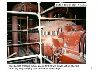
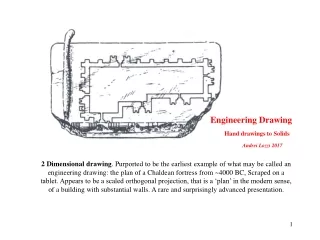
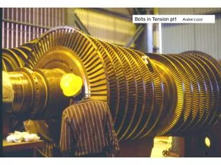
Bolts in Tension pt1 Andrei Lozzi. The flanges at the end of the two turbine shafts seen above, are bolted together to form a very rigid friction coupling.

E N D
The flanges at the end of the two turbine shafts seen above, are bolted together to form a very rigid friction coupling
High pressure turbine casing. Note the proportion of the depth of the flanges to the bolts diameter. Note also the spacing of the bolts. This is one of the most extraordinary bolted joint.
These are the heater elements used to ‘grow’ the length of the bolts. When left to cool and the bolts reaches the same temperature as the flanges, they develop the required preload
The stem of the bolts is held from turning while the nut is torqued up. Holding the end of the stem prevents torsional stresses being transmitted to the stem.
Note that the stem of these bolts have flat faces machine into their ends, allowing the stem to be held while the nut is torqued. Also the ‘stem’ is really a threaded bar
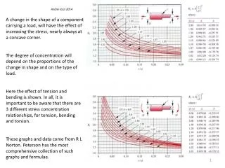
Simple variations in the detail design of the threads, nuts and bolts in a search to improve fatigue strength
Results in stress concentration from the above detail designs variations
The effect of fillets and bolt shank cross-section on fatigue strength
The effect of the reduction of the bolt shank cross-section by inserting fillets at the start of the threads.
Improvements in fatigue life by increasing radius of fillets at the base of external thread
Bolted joints may use a small number of large dia bolts, with wide and thick flanges or a large number of small dia bolts and small flanges. We must also choose the shape and strength or grade of the bolt. Near one extreme we get the cheapest joint, near the other the lightest. Exactly the parameters of each is very difficult to determine without something like a ‘solver’. In individual industries there has been a tendency to select a combination and stick with it, now thanks to MS it is possible to obtain numeric optimal solution for each application.
Villiers two stroke engine. In low performance and low efficiency engines one finds simple means of sealing the engine head to the cylinder and thereby containing the combustion products. Here a simple paper gaskets are used both at the head and at the cylinder to crankcase joints. Paper has about 1/2000 the Young’s modulus of iron. Hence the stiffness of the assembly is very poor and the alternating loads on the bolts is not helped much at all by the cast iron cylinder
Clearance bolt hole Washer dia 30° cone Bolts do generate uniform pressure over the whole face of a flange. In fact they only clamp around a cone of 30 ° and then even there the pressure is not uniform. The flanges interface separates away from this cone. The separation occurs because under compression the flange material expands laterally. This effect may be seen on the FEA example shown below. Any gasket or sealant must be able to fill the gap with sufficient strength to prevent any leak. Cones in compression
Coventry Climax, 2 liters 4 cyl, 62 The ‘head’ of this engine is removable. To seal the combustion products a reasonable even pressure has to be maintained all around the interface between the cylinder block and the head. Cylinder head Interface head to cylinder block. Cylinder head hold-down studs To achieve this the studs begin half way through the cylinder block and extend all the way to the top of the engine. Each cylinder has 4 bolts equally disposed around its periphery. By this sort of strategy the conical compression zones generated by the pretension has space to spread from the middle of the cylinder block, to all around the top of the cylinder and meet similar cones coming from the head.
These bolts have to hold the tower segments together, when subjected to fluctuating wind loads (among other loads)