Download
1 / 24
240 likes | 255 Vues
Explore progress, challenges, and future plans for optimizing cryogenic LH2 absorber and vacuum window designs, focusing on safety, heat extraction, and thermal stability. Detailed information on testing, measurements, and system integration efforts.

E N D
LH2 Absorber Review R&D Motivation Windows (absorber and vacuum) Absorber manifold designs and flow tests System integration Near term plans Summary
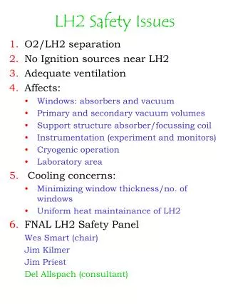
Mucool LH2 Absorber Issues Approx. eq. for emittance: • Minimize scattering • Nonstandard window designs for absorber and vacuum vessel “SOLVED” Maximize heat extraction Optimal cryogenic designs IN PROGRESS Temperature and density stability: LH2 circulation UNSOLVED • Safety • No H2/O2 contact: containment, ventilation, controls IN PROGRESS • No ignition sources: instrumentation must be “safe”, RF cavities “benign • System Integration • Confined operation, large B fields: system integrity and stability IN PROGRESS • Temperature range from room to Lhe: condensation issues
Measuring the “thinnest” thickness • Two different radii of curvature • Possibly not concentric Modified torispherical design If not at the center, where?
Windows tests } • Procedure (for manufacture quality control and safety performance) Three innovations: • Precision measurement of window: photogrammetric volume measurements • FEA predictions: inelastic deformation, 3 – dim included in calcs. • Performance measurement: photogrammetric space point measurement Non-standard thin window design: No closed form expression for maximum stress vs. volume pressure FEA (finite element analysis): geometry stress material strain volume pressure displacement • Progress towards meeting FNAL Safety Guidelines • Absorber and vacuum window guidelines understood • Absorber window test completed • FEA/data agreement established
Photogrammetric measurements Strain gages ~ 20 “points” CMM ~ 30 “points” Photogrammetry ~1000 points
Photogrammetry • Contact vs. non-contact measurements (projected light dots) • “Several” vs. ~ thousand point measurements (using parallax) • Serial vs. parallel measurements (processor inside camera) • Larger vs. smaller equipment • Better fit to spherical cap. • Updating camera and methods to prepare for “production mode”
Window shape measurement D. Kubik, J. Greenwood Convex Concave CMM data points Whisker = z(measured)-z(design)* *Given the design radius of curvature of the concave and convex surfaces, z(design) was calculated for the (x,y) position of each target
130 m window Rupture tests “340” m window Burst at ~ 120 psi 1. 3. Leaking appeared at 31 psi ..outright rupture at 44 psi! Burst at ~ 152 psi 2. 4. Burst at ~ 120 psi “350” m window Cryo test
Window # Test temp. FEA results Test results Minimum window thickness (mm) Rupture pressure (psi) Window thickness from CMM (mm) Measured rupture pressure (psi) 1 293K 0.13 48 0.114 42 2 293K 0.33 117 0.33 119 3 293K 0.345 123 0.345 120 4 80K 0.33 156 0.33* 152 • Performance measurement (photogrammetry) 1. Room temp test: pressurize to burst ~ 4 X MAWP (25 psi) 2. Cryo test: a) pressure to below elastic limit to confirm consistency with FEA results b) pressure to burst (cryo temp – LN2) ~ 5 X MAWP fromASME: UG 101 II.C.3.b.(i) Absorber window test results Discrepancies between photogrammetry and FEA predictions are < 5%
FNAL Requirements: • Burst test 5 vacuum windows at room temp. to demonstrate a burst pressure of at least 75 psid for all samples. (pressure exerted on interior side of vacuum volume). • Non-destructive tests at room temperature: • External pressure to 25 psid to demonstrate no failures: no creeping, yielding, elastic collapse/buckling or rupture • Other absorber vacuum jacket testing to ensure its integrity Vacuum Windows Vacuum “bellows” window (34 cm diam): No buckling at 1st yield (34 psi) Internal pressure: burst at 83 psi
LH2 Window R & D Immediate future: Manufacture and test of 21 cm “bellows” absorber window Manufacture and test of 34 cm vacuum window – internal and external pressurization *new test* New aluminum alloy (stronger) Optimize seals to manifold Stability test in the Lab G magnet **
Convection absorber design Internal heat exchange: Convection is driven by heater and particle beam.Heat exchange via helium tubes near absorber wall. Flow is intrinsically transverse. Output from 2-dim Computational Fluid Dynamics (CFD) calcs. (K. Cassel, IIT). Lines indicate greatest flow near beam center. KEK prototype, S. Ishimoto
Force-flow Absorber External heat exchange: Mucool ~ 100 - 300W (E. Black, IIT) Large and variable beam width => large scale turbulence Establish transverse turbulent flow with nozzles E158 design: Mucool design:
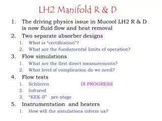
LH2 Manifold R & D The driving physics issue in Mucool LH2 R & D is now fluid flow and heat removal Two separate absorber designs “Pre-MTA” test (2003) : convection MTA operation (2004) : force flow Flow simulations 3 dim FEA CFD Flow tests Instrumentation
LH2 flow issues… Our Challenge: Large heat deposition and beam path is through entire volume absorber! 1. Liquid must move everywhere, particularly in window volumes 2. Need gauge of temperature and density uniformity Questions: What is testable? How quickly can simulations be verified by experiment? What tests will be useful, and how quantitative can they be? What level of instrumentation will convince us of sufficient temperature uniformity?
3 dimensional FE simulations are possible but CPU intensive (W. Lau, S. Wang) Force flow simulations 3-dim and 2-dim flow simulations are consistent – use 2 dim for design and iteration. Preliminary results indicate that “bellows” window has better flow pattern in window volume.
Liquid Hydrogen Heating Coil Lau/Wang FE 3-d flow simulation of KEK LH2 absorber: Convection flow simulations 3-d grid: K. Cassel CFD:
Schlieren testing of convection flow (water) test at ANL (more quantitative program to run in 2003) J. Norem, L. Bandura Flow Tests
MTA Prestage with KEK absorber • LH2 setup and system integration • Absorber manifold and containment will be ready before the MTA! • Exercise filling and purging of absorber • Readout of temperature probes as a first verification of temperature maintenance via convection • Instrumentation readout • Can establish heat loading capacity sufficient for MICE requirements UNSOLVED
MTA LH2 Experiment Lab G magnet LH2 Cryostat RF cells Beamline: C. Johnstone
Mucool Test Area LH2 Setup Lab G magnet
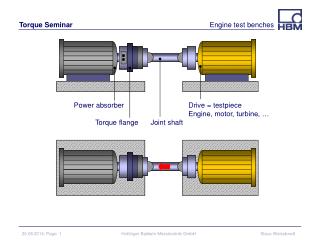
MTA Force Flow Cryo System Red - HydrogenBlue – Helium Based on E158 LH2 target system
Mucool 2003/2004 Absorber/vacuum windows manufacture and test Fluid flow/convection simulations Instrumentation and data acq. development Flow tests: Forced Flow, Convection Safety Review MTA test design finalization MICE design Japanese absorber pre-MTA LH2 run Absorber/Solenoid Tests 2004 MTA LH2 absorber staging
Summary Comments On LH2 R & D We have an established window design/manufacture/certification program, for absorber and vacuum windows, completed tests on the first window prototype, and have made many technical improvements on design. We have developed new applications for photogrammetry (NIM article(s) in progress!) Several projects have developed from LH2 absorber concerns, ideal for university and student participation. MICE participation has advanced the Mucool program: the two absorber designs are complementary; integration problems are being solved – possible hybrid absorber for a real cooling channel likely. The above four points means that we have survived as a program the delay of the FNAL MTA construction – (KEK in “prestage” LH2 tests could help) LH2 flow and heat conduction has now become the dominant physics concern for the absorber. The two flow designs will be pursued in parallel. LH2 safety is the dominant engineering concern for the cooling cell, but there has not yet been any show-stopping problems.