Development of Efficient and Eco-Friendly Coal Combustion Systems
460 likes | 514 Vues
Explore historical insights and modern technologies for optimizing coal combustion. Learn about pulverized coal systems, grate-fired furnaces, and the eco-friendly methods for large-capacity combustion. Discover key theories and advancements in coal combustion engineering.

Development of Efficient and Eco-Friendly Coal Combustion Systems
E N D
Presentation Transcript
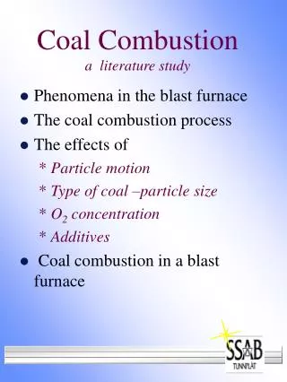
Pulverized Coal Combustion Systems P M V Subbarao Professor Mechanical Engineering Department Efficient & Eco-friendly Methods for Destruction of Entropy Vehicles…..
Traditional Coal Combustions System: Fixed Fuel Bed Combustion O2+CO2+N2+H2O Flame Secondary Air VM+CO+CO2+N2+H2 Green Coal Incandescent coke CO+CO2+N2+H2 ASH Grate Primary Air
Salient Features of Grate Fired Furnace • The grate heat release rate is < 1.3 MW/sq.m. • Size of coal pieces: 19 mm to 38 mm. • Only suitable for free burning coal. • Max. ash allowed is 20%. • Largest capacity possible : 155MWth. • Maximum steaming rate: 50kg/s. • Huge pressure drop across fuel bed. m U (1- e)2 rg U2 (1 – e) Dp = 150 + 1.75 (fdp)2e3 fdpe3
In the early 1900s, a 50MW(e) plant (considered large at that time) housed five 10 MW steam turbines and typically required 50–60 boilers to power the turbines . The Big Challenge: How to develop eco-friendly & large Capacity Coal Combustion Systems ?????
The Law of Learning one fourth from the teacher, one fourth from own intelligence,one fourth from classmates, and one fourth only with time. Mahabharath
Duties of A Furnace : By Dixon • Dixon’s Theory: • Generate an environment of excited fuel and oxygen molecules. • All the fuel molecules should be surrounded by oxygen molecules. • Facilitate frequent collisions among excited fuel molecules and excited fuel molecules. • A successful collision can lead to combustion. • Development of suitable technologies is the need for efficient combustion of fuels (coals).
Five Requisites for Good Combustion • MATtr Theory: • M : Proper mixing of the reactants. • A: Sufficient air. • T: Conducive temperature • t: Sufficient time • r: Satisfactory local density of reactant.
Reduction of Combustion Time • How to increase the interaction among fuel and oxygen molecules? • Combustion of solid fuel is heterogeneous reaction. • Rate of combustion is proportional to surface area of fuel particle available for oxygen. • Two Major solutions: • Fluid Mechanics based solutions. • Simple geometric solution. • For same mass, lower diameter particles will have more surface are than larger particles. • Grinding the particles will enhance the area of exposure. • This will also reduce Overall Coal Combustion time.
Realization of MATtr Theory • Mixing: Fuel preparation systems. • Air: Draught systems. • T : Preheating of fuel. • t : Dimensions of combustion chamber. • : Turbulence generation systems.
Fluid Mechanics of Solid Fuel Beds Floating Bed Dynamic Bed Static Bed Dp Velocity
Pulverized Fuel Combustion • In the 1920s, the pulverized coal firing was developed. • This process brought advantages that included a higher combustion temperature, improved thermal efficiency and a lower requirement for excess air for combustion. • An universal choice for power plants till 1990. • Fine particles of coal ~ 75 microns. • Surface area : 150 m2/kg. • Huge heat release per unit area : 2 – 5 MW/m2. • Steam generation : ~ 2000 tons/hour.
The One & Only One, Which Made it Possible? • Cement industry uses pulverizers to grind lime stone. • The coal is ground and dried in an hot air-swept mills. • These mills are equipped with aerodynamic air-solid separators (classifiers). • The pulverized coal is pneumatically transported to burners. • The coal-air mixture is injected in the form of particle-laden jets into the combustion chamber. • Among the most challenging fluid mechanics problems are those dealing with preparation of the coal prior to combustion.
Current Three Ts & One S Practices Size the Coal and Add the Air !!!
Current Three Ts & One S Options for Coal Combustion Size the Coal and Add the Air !!! Åagisza power plant (460-MW ) began commercial operation in late June 2009, it marked the beginning of a new era in the evolution of circulating fluidized bed (CFB) technology.
Eco-friendly Air Distribution System for PC Combustion Furnace ~250C ~350C Coal+ Primary air 75 - 90C Rotary Air Preheater Pulveriser FD Fan Tair,amb ~140C
Duct SCAPH APH APH ESP ID Fan Wind Box FD Fan Duct Duct Boiler
Stockholm 1920The Ljungström Air Preheater The first installation in a commercial boiler saved as much as 25% of the fuel consumption.
Historical Significance of Landmark • In a modern Steam generator the Ljungström Air Preheater provides up to 20% of the total heat transfer in the boiler process. • The Ljungström Air Preheater only represents 2% of the investment. • The Ljungström Air Preheater is a remarkable invention in many ways. • It saves the fuel so much that the cost of the preheater is generally recovered after only a few months. • It has been estimated that the total world-wide fuel savings resulting from all Ljungström Air Preheaters which have been in service is equivalent to 4,500,000,000 tons of oil. • An estimate shows that the Ljungström Air Preheaters in operation annually saves about $30 Billion US.
The Idea: One Shot Two Birds Data for the hand fired boiler before and after the installation of Ljungström Air Preheater is as follows:
Realization of MATtr Theory • Mixing: Fuel preparation systems. • Air: Draught systems. • T : Preheating of fuel. • t : Dimensions of combustion chamber. • : Turbulence generation systems.
Physical Structure of Coal Mill Crushed to small pieces of about 20 mm diameter
The classification of solid particles according to their size in the spiral house of a cyclone is illustrated by Figure. Coal Particle Classifiers • The particles can migrate toward the outer wall or the exit tube; • From the force balance on a particle and knowing the path of the gas in the cyclone, the radius rlcan be determined, which will be the limiting radius for the radial penetration of a particle of diameter, d.
Fluid Dynamics of Particle Classification • At values of r > rl, the centrifugal force grows faster than the radial component of the gas velocity. • The limiting radius can be given as : where d is the particle size, mm, rp is particle density, vt,0 istangential inlet velocity to the cyclone, r0 is the cyclone radius, m the dynamic viscosity of the air. The limiting (smallest) particle size precipitated can be given as
Drying of Coal Particles in Pulveriser – Stage 1 Overall Mass balance Equations – Water in Coal: • Mass balance equation for water in coal is considered in bowl-grinding zone together where water enters from raw coal and recirculated coal falling from bowl and separator zone. • This coal with water is then entrained by hot air and coal with water moves to the separator zone. • It is assumed that coal is well mixed so the moisture fraction is the same for all sizes of coal particles. • The mass balance equation for water in coal is represented as follows:
Drying of Coal Particles in Pulveriser – Stage 2 • In the separator zone during the suspension period, air transfers some of its thermal energy to the coal and causes the further drying of coal particles. • Drying is reduced to separator zone only. Moisture in dried coal moving to the classifier is determined by the following equation:
Hot air Heat loss Puliverizer frictional dissipation Dry pulverized coal + Air + Moisture Coal Motor Power Input Mill Energy Balance Tempering Air, Tatm
Mill Operation Window Erosion Limit PC Transport Limit Milling Capacity Limit Drying Limit Tampering Limit
Suggested Moisture Level in Coal at Mill Exit Min Mexit
Moisture Content in Coal at Mill Exit Moisture removed in Mill:
Transport of coal particles from Mill to Furnace • Pneumatic conveying of coal particles are known as flows with low-solids concentration ("dilute-phase flow"). • The ratio of coal to carrying gas is determined by systems and combustion considerations and is usually in the range of 0.5-0.6 kg of coal/kg of air. • Assuming a coal density rc = 1.5 x 10³ kg/m3, and the density of the carrying gas as rg = 0.9 kg/m3, the volume fraction of the coal can be shown to be very small, 0.036 %.
Coal Particle Transport Velocity • An important aerodynamic characteristic of the particles is their terminal velocity. • This is defined as the free-fall velocity in stagnant air. • For a spherical particle of d = 100 m has an approximate value of Vt = 0.3m/sec. • Local velocities of air flow must impart a velocity to coal particles. • If Vparticle < Vterminal : Falling of particles • If Vparticle = Vterminal : Floating of particles • If Vparticle > Vterminal : Transport of particles • Due to non-uniformities of flow behind bends, and to avoid settling of solids in horizontal sections of the transport line, a minimum air velocity of V = 16 - 20 m/sec is recommended.
Coal Pulverizers A Inlet Duct; B Bowl Orifice; C Grinding Mill; D Transfer Duct to Exhauster; E Exit Duct.