Information Coding for Transmission (Images, Data, Error Protection)
Information Coding for Transmission (Images, Data, Error Protection). Southern Methodist University/ National Technical University EETS8302/TC716N Fall 2003 Lecture 13 Slides only. (No notes.). Modems and Modulation.

Information Coding for Transmission (Images, Data, Error Protection)
E N D
Presentation Transcript
Information Coding for Transmission (Images, Data, Error Protection) Southern Methodist University/ National Technical University EETS8302/TC716N Fall 2003 Lecture 13 Slides only. (No notes.)
Modems and Modulation • Digital information is transmitted via some physical waveform with a parameter (voltage, optical fiber light intensity, etc.) varying to represent different coded values • The process of varying such a parameter is called modulation. A device which performs this operation is a modulator. A device which performs the reverse operation, namely recovering the digital code value from the waveform, is a demodulator. • A jargon term for a device which includes both functions (one for transmit, the other for receive) is a modem, from the italicized initial parts of the two names.
Sine Wave Carrier • In many applications, a basic sine wave is used as the “carrier” waveform for the information • Historically, radio transmitters utilized analog modulation on a sine wave1 for voice long before digital transmission • Historically, voice telephone carrier transmission systems used frequency division multiplexing (FDM); similar to radio, but via wires • In these situations, engineers’ thoughts turned naturally to use of modulated sine waves for data communication as well • To convey information, these properties of a sine wave are modified: • Amplitude (modify the voltage up or down ): AM • Frequency (modify the number of cycles per second): FM • Phase (modify the time delay or advance of each oscillation cycle relative to a reference or comparison sine wave of the same frequency): PM or M 1 The earliest radio transmitters used “noisy” oscillators (spark gap devices) which could not produce a “pure” sine wave. When electronic oscillators producing a “pure” sine-wave were introduced, their output was called “continuous wave” or CW.
Modulation of a Sine Wave volts L H time unmodulated Phase (PM or M) H G K H Ampliude (AM) Amplitude & Phase (QAM) Frequency (FM)
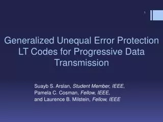
2 M 1 -1 G H 2 -2 1 L -1 Constellation Diagrams • Discrete PM, QAM (and occasionally AM) symbols can be represented by points on a constellation diagram • FM can be represented by a continuously changing phase, a circular line, rather than point(s), on a constellation diagram. • Example constellation here has 25 points. Most practical constellations have 4, 8, 16, 2N… in general, and some are not “square” • With 8 points, each point symbol represents 3 bits, with 16 points, each symbol represents 4 bits, etc. Quadrature-phase, 90°, or Sine axis In-phase, 0° or Cosine axis K -2
Amplitude Modulation Examples • Analog AM is used in the long, medium and short wave radio bands • A special version of analog AM called Single Side Band (SSB) is used for military, amateur (“ham”) radio, and for historical telephone FDM systems • Simple AM has twice the bandwidth per channel of the original ‘base band” signals (thus 8 kHz radio bandwidth for a 4 kHz bandwidth telephone grade voice signal). SSB has the same bandwidth (4 kHz) and uses less RF power as well. • The simplest form of digital AM is on/off carrier “keying.” Morse radio telegraph is an example using Morse* (not binary) code • Because of sensitivity to interference from other radio signals, digital AM is not used in most practical systems. *Strictly speaking, Continental radiotelegraph Code, a modification of the original hisstorical American Morse-Vail code.
Frequency Modulation Examples • Analog FM was invented by the prolific radio inventor Col. Edwin H. Armstrong, in the 1930s. • Used for FM broadcasting (88-108 MHz VHF band) and for TV sound, and for analog cellular radio voice. • Simple digital FM is called Frequency Shift Keying (FSK); uses instantaneous shifts between discrete frequencies. • Used in low bit rate modems (103 and 202 type), and for control signals associated with analog cellular, etc. • Early telephone-line modems used different sub-bands of the 3.5 kHz audio bandwidth to prevent interaction between the originating and answering direction modem signals • Several methods for gradual shift between frequencies are in use, such as minimum shift keying (MSK), Gaussian MSK (GMSK- used in GSM/PCS-1900 etc.), etc.,which minimize radio emission outside of the desired bandwidth • All above are nominally binary digital FM. • Quaternary (4 level) FM is also used in some pocket pager radios, etc.
Phase Modulation Examples • Phase modulation is seldom used alone for analog signals • FM can be indirectly produced by 1) time-integrating the base band source waveform, and 2) using it to phase modulate the carrier, since frequency is the time derivative (time rate of change) of phase. (Method used by Armstrong in 1935) • Digital PM is used in various military and other radio data communication systems, and also in • CDMA (IS-95) (uses both CDMA coding and PM) • TDMA (IS-136) digital cellular • EDGE digital (2+1/2 G) cellular • In IS-136 (and its historical predecessor, IS-54) the phase modulated signal is post-filtered to minimize the amount of radio power transmitted in adjacent frequencies. Radio signals passing through this special filter self-oscillates slightly producing an incidental but inevitable variation in the amplitude. That does not imply that other PM systems have incidental AM as well.
QAM: Combined AM and PM • A combination of both AM and PM allows several bits to be encoded into one symbol. • Example: 4 phase angles and 2 amplitude levels allow 8 distinct symbols, which can encode 3 bits/symbol. • Use of a higher number of phase angles and amplitude levels also makes the signal more susceptible to interference and noise. • Most modern telephone-line modems (V.32, V.34 etc.) use QAM • Also proprietary Motorola iDEN (Nextel) digital 800 MHz SMR= Specialized Mobile Radio) band radio system • Also ADSL, using QAM on multiple simultaneous distinct carrier frequencies (DMT= discrete multi-tone) • Digital adaptive echo-canceller methods utilize the full ~3.5 kHz audio telephone channel bandwidth in both directions simultaneously for modern telephone line modems
Bits/second and baud • The data rate is the number of bits/second • The symbol rate is the number of symbols/second, measured in baud (abbreviated Bd, named for Emile Baudot, the 19th c. French inventor of an early teletypewriter) • If the binary data is modulated using only two values of the modulation parameter, then there is one “symbol” for each binary bit • For such a 2-level system, the baud rate is equal to the bit rate • If a combination of parameters such as in multiple angle PM or in QAM, then there are several binary bits per symbol. If the modulation design permits 2N distinct symbols, then each symbol encodes N bits • Thus, 4 distinct symbols allows 2 bits/symbol • 8 distinct symbols allow 3 bits/symbol • 16 distinct symbols allow 4 bits/symbol • 32 distinct symbols allow 5 bits/symbol
56 kb/s PCM modems • Several proprietary and incompatible 56 kb/s modems have been on the market since 1997. An ITU standard V.90 is now available. • Vendors all have free or low-cost upgrade of earlier proprietary modems to the V.90 standard • One end of the telephone link must be a truly digital terminal (so-called DS-0 channel derived from ISDN BRI or a single channel from T-1). It uses 128 distinct amplitude symbols, with 7 bits/symbol, in theory. • These modems do not use a sine wave carrier with QAM. A cyclic binary coding algorithm is used so the waveform will not dwell on just one voltage level of the Mu-law signal for successive equal binary data values. • To get the full 56 kb/s, all 128 amplitude symbol values are exercised (depending on data values). This would possibly occasionally transmit audio with +2 dBm or more loudness, causing severe crosstalk. Current FCC regulations limit the amplitude and thus limit the data rate to 53 kb/s. In many noisy lines, the real data rate is even lower.
ISDN “U” Interface • ISDN basic rate interface (BRI) service can be provided on most existing subscriber loop twisted pair wire by installing an ISDN subscriber loop card in the central office switch. Loop length limitations are typically shorter (e.g. 2 km) than analog loops. • In North America, 192 kb/s digital signals are transmitted both ways on ordinary telephone wire using a 4-level voltage symbol with 2 bits per symbol (2B4Q). A cyclic binary coding algorithm is used so the waveform will not dwell on just one voltage level of the four for successive equal binary data values. • U interface signals in Europe are different in different countries, where the Telco provides the NT1 interface box at the customer premises • The physical and signal protocol used on the subscriber side of the NT1 ISDN box is the same regardless of the national U interface coding. • Digital adaptive echo cancellers are used to provide simultaneous 192 kb/s two way transmission while preventing interaction between the subscriber and central office transmitted signals • Where clear channel transmission is available via the inter-switch digital part of the transmission path, Basic Rate ISDN can provide two 64 kb/s channels end to end. Otherwise, in North America, 56 kb/s is available everywhere without clear channel transmission facilities.
xDSL Methods • Twisted pair telephone wire has more severe loss for the high frequency components of high bit rate signals, but there is no absolute upper limit on the frequency carried • HDSL* uses a multi-level voltage signal to carry 1.544 Mb/s digital signal (T-1) via 8 km (5 mi) of ordinary single pair (no repeaters are used). These signals do not pass through normal telephone switching equipment, but use special high-bit-rate apparatus which connects to the subscriber loop wires (Digital Subscriber Line Access Module - DSLAM). • Standard telephone service can be provided simultaneously on the same wires with some xDSL** signals. Some systems use passive frequency filters to separate the xDSL signals from the POTS baseband audio frequencies. Some xDSL equipment produces little audio frequency range power so that filters are alleged to be not required (“ADSL-lite”). *High-rate Digital Subscriber Loop **Initial letter x stands for A or H or other abbreviation as a class of similar technologies.
ADSL* • Can provide up to 6 Mb/s in one direction, perhaps up to 1 Mb/s in other (both bit rates depend on loop length, local interference level, etc.), as well as supporting ordinary telephone service on same wire pair • An existing standard (discrete multi-tone: DMT) uses simultaneous sine waves at different carrier frequencies. Each one is individually phase and amplitude modulated. • A historical competing but not standardized proposal was carrier-less amplitude-phase (CAP), a single carrier frequency QAM-like technology. • DMT equipment continually examines the various frequencies during use, and abandons those with bad interference (crosstalk from other wires, etc.) and assigns other frequencies, always choosing those carrier with best signals • ADSL supports many existing and proposed services: • High bit rate data services: Internet, etc. (most popular current purpose) • Digitally coded entertainment video, etc. (historical original purpose) • Hardware cost is high and has not decreased with experience as much as desired, and competitive technologies like cable modems and satellites are strong competitors. ADSL maximum loop length is presently ~15000 feet. *Asymmetric Digital Subscriber Loop
Echo Cancellers and Adaptive Equalizers • All these modem devices utilize internal adaptive equipment (often implemented using DSP – Digital Signal Processor -- technology) to identify undesired delayed replicas of the incoming signal (for adaptive equalizers) or the outgoing signal re-appearing at the input (for echo cancellation), and then substantially cancel that undesired signal with an internally constructed delayed “inverted” waveform. • In digital cellular and PCS radio systems, delayed signals (due to multipath radio propagation from reflections of the radio waves) are treated via adaptive equalizers also (called “RAKE receivers” in CDMA radio equipment)
Source Encoding • Objective: Reduce bit rate yet convey specific types of (usually redundant) information accurately • English or other natural language text • Certain characters (letters) in e.g. ASCII binary code, certain words or even entire phrases are frequently repeated • Fax images (black/white) • Many small portions of the image contain vertical or horizontal lines, so parts of some line scans are identical • Large solid white (or black) areas produce many consecutive binary 1s or 0s. • Gray scale or color images or moving images • Aside from redundant information, we also exploit continuity (areas of uniform color, or very gradual spatial changes in color) • Small frame-to-frame changes in sequence of moving picture images • General digital information • Example: computer program in binary “object code” form. May or may not have highly redundant information
From Morse to Huffman • Morse code (using dots and dashes) was jointly invented by Samuel Morse and Alexander Vail • By examination of a printer’s case of type characters, Morse and Vial recognized that letters like E T A I N M are frequently used, while J Q Z etc. are least used. (the Mergenthaler Linotype keyboard similarly used ETOAIN SHRDLU on the first two rows) • Shortest Morse code symbols were assigned to the frequent characters, longest to the infrequent. E=•, T=-, A=•-, J=•--- • Consequently the time required to transmit ordinary English text is minimized • Use of other languages (e.g. German) would not be maximally efficient (for example, c only occurs before h or k in native German words, far less often than in English). Consequently, a modified “continental” telegraph code was developed in Europe with different (shorter) symbols for “c” and other letters. Continental code is the surviving form of Morse code still used today by amateur and other radio operators.
Huffman Coding • A formal procedure for assigning binary codes of various lengths. Optimal for some data populations. • Example: for 4 symbols A, B, C, D. Trace branches from “start” to the symbol; sequence of binary digits is the code. • Code for A = 0; for B =10; for C =110; for D =111 • This code is optimal if the relative proportion of A B C D in the population of messages is respectively 1/2; 1/4; 1/8; 1/8. For other proportions it is sub-optimal • Prof. David Huffman (died 1999) of U.C.Davis invented this while a student at MIT, for a course term paper. A B C 0 0 0 D start 1 1 1
Lempel-Ziv-Welch (LZW) • LZW is a continuously adaptive encoding system • The late Terry Welch (MCCC, Austin TX) implemented a practical general purpose system based on the research of Lempel and Ziv (Weitzmann Institute, Rehovot, Israel) • PKZIP, by the late Phil Kauffman, (and WinZip) the popular data file compression software programs, use LZW technology • Simplified explanation: Transmission starts with a Huffman code based on English ASCII text. Different codes are assigned “on the fly” as more data accumulates about the relative occurrence of each character • Both the transmitting encoder computer and the receiving computer do these changes simultaneously • This continuous updating of the code conversion tables requires an error free channel! Otherwise decoder and encoder tables will not remain the same.
Compound Data Compression? • Certain types of data do not “compress” well: • Data in which all (e.g. byte size) bit patterns occur equally often. No redundancy! • The output of a “good” LZW data compression is typically without significant redundancy, and cannot be further compressed • A code dictionary has a shorter symbol (binary number value) for each of many (expected) long messages • Code dictionaries of frequently used business phrases were popular historically when telegrams were billed by the word • Examples: “73” represents “Best Wishes” • “88” represents “Love and Kisses” • “ARDOK” represents “ship immediately via rail” • These codes were not used for secrecy. British and US telegraph law permitted only use of openly published code books. • Code book compression is theoretically interesting for certain applications, but in practice requires huge and often impractical code dictionaries for general compression.
Image Coding: Pre-processing • 2-dimensional images are first converted into one-dimensional arrays of pixel (picture element) or pel information via horizontal line scanning, for encoding and transmission • Analog TV broadcasting, fax • Simple Binary Digital encoding of black/white into binary 1/0 values for fax. • Gray scales, or brightness level of three (R G B) separate color-separation images are digitized with typically 8 bit uniform code (no Mu-law compander here) • Digital picture coding (MPEG, JPEG) uses an intermediate step of dividing the image area into smaller squares, each perhaps 100x100 pixels. The data derived from some of the squares is then transmitted serially.
Raster Scanning Arrows indicate direction of motion of scan spot. The grid of horizontal scan lines is called a “raster.” end line 1 end line 2 etc. start “flyback” rapid reverse motion of scan point is present in television, not in most FAX machines. Diagram above illustrates so-called “progressive” or “continuous” scanning, used in FAX and some computer generated graphics. Group 3 FAX systems scan 96 lines per vertical inch. end line 1 end line 2 end line 3 etc. Second diagram illustrates so-called “interlaced” scanning, used in analog TV. Odd numbered lines are scanned first, producing a “field.” Then even numbered lines are scanned to produce a second field. The two fields together make a “frame” and fill in the full quantity of scan lines. This reduces the perceived visual flicker. TV in North America* and Japan uses the National Television System Committee (NTSC) standard, 525 scan lines per frame, 30 frames/second. Most other countries use the phase alternating line (PAL) or sequentiel coleur avec memoire (SECAM) standards, both with 625 lines/frame, 50 frames/second. [*for radio/TV, “North America” includes Mexico and parts of Central and South America.]
Scanning Methods • Early FAX machines mechanically moved a single photocell over the surface of the paper via a rotating cylinder or oscillating light spot projector • Modern fax machines may use a combination of mechanical motion (vertical direction) and an array of light sources (light emitting diodes) or photo receptors • Television cameras originally used electron beams to scan a photo-emissive metal surface (potassium, cesium etc.) • Modern TV cameras use arrays of photo receptor diodes which are scanned by electronic digital switching technology. For color information, diode imagae arrays are fabricated with different color sensitivity (different alloy doping producing different light/wavelength sensitivity)
Modern FAX Methods • ITU T.30 standard describes Telefax (telephone facsimile). Historically four systems exist: • Group 1: original 1960s Xerox telecopier. Mechanical scan of original document on a rotating cylinder. Analog FM representation of brightness levels. Obsolete. • Group 2: early digital system, with data compression coding. Obsolescent. • Group 3: Major digital data compression methods used today to transmit a page in less than 1 minute. Digital data rate of 9.6 kb/s via modem normally used, but lower (2.4 kb/s) and higher rates (14.4, 28.8 kb/s) are also used. • Group 4: Normally associated with 64 or 56 kb/s digital links, ISDN. Versatile data formatting permitting different pel density (e.g., 300 pel/inch to match laser printers, etc.), supports line printer (ASCII codes) as well as images, etc. etc. • Other aspects of T.30 standard permit manual answer, start, paper feed, automatic adjustment of data rate for “noisy” connections, etc.
Data Compression in FAX • Three major data compression methods are used in Group 3 FAX: • Scan line difference computation • Used due to presence of many vertical lines in English text characters and other images • Often produces long runs of 0 in the computed difference of two successive horizontal scan lines • Run length coding • Particularly useful following line difference computation • Useful due to long runs of 1 or of 0. Described instead by a binary number specifying the length of the run. Compresses data bits in proportion to log2 of the run length. A run of 2047 pels can be represented by 11 bits with a suitable prefix. • Huffman Coding • Not all older Group 3 machines do “Huffman,” so some run slower. Newer FAX machines compute Huffman codes since memory and processor chips are now low cost.
Gray Scale & Color. Motion Pictures • Photograph-like images are typically encoded using JPEG and MPEG* coding • A major feature is Discrete Cosine Transform (DCT), a two dimensional Fourier analysis of the brightness information, for each primary color, into horizontal and vertical cosine waves • Motion pictures use frame-to-frame difference calculation to avoid transmitting redundant data describing stationary parts of the image • Example: A news reader in front of a static background has motion only in the face and possibly hands. • Motion Compensation exploits translation (movement without rotation) of objects in the image by describing the translation vector for various sub-squares in the picture, and then transmitting the difference between this translated square of the picture and the actual image *Joint Photographic Experts’ Group; Motion Picture Experts’ Group
Discrete Cosine Transform • Representation of one monochrome two-dimensional cosine wave brightness pattern • Simplest cosine term is a 0,0 or constant brightness square (not shown) • After Fourier analysis, the coefficients of each cosine term are transmitted digitally • Some coefficients are omitted totally if their value is small. This produces a picture lacking certain details but still acceptable to the human eye, particularly when scene changes rapidly. Illustration represents case of a full wavelength horizontal, and a half wavelength vertically, in one square. Many other higher order spatial 2-dimensional cosine patterns are also used for DCT. brightness distance
DCT Results • Typical video image is divided into many small squares for analysis • Each square is analyzed and represented as the “brightness” coefficient of each appropriate cosine pattern for each primary color as well • Coefficients are transmitted and image is built up starting from longest spatial wavelength cosines. Image details only are visible when shorter spatial wavelength terms are included • Example: overall brown color of a wood table is immediately visible, but details of the wood grain only appear after a few seconds.
Lossy Codes: Exploiting Eye Properties • The human eye cannot distinguish color in areas of fine detail • Due to distinct light-sensitive rods (brightness sensitive elements mainly in the macula or central field of vision) and cones (color sensitive elements mainly in the outer field of vision) in the retina • This property exploited in analog and digital color TV • Low pass analog filter used on video waveform in analog TV removes small fine details • Highest spatial frequencies (shortest wavelengths) omitted in DCT • 3 “primary” colors simulate the true color spectrum • A rapid sequence of still pictures produces the illusion of continuous motion • A result of “persistence of vision” (the eye’s light receptors low-pass time-filter brightness waveforms) • The eye cannot distinguish sharp focus from lack of focus in a rapidly changing scene • This property exploited when DCT builds up gross areas of color during first fraction of a second, then increases detail later
Motion Compensation Example • If the news reader suddenly stands up from an initial sitting position, the squares which include the head and shoulders will be copied into the position of squares above their initial position • Later the discrepancies between the shifted/translated head and the actual appearance of the scene will be filled in (incorrect extrapolations shown in pale green) • The portion of the torso which was originally hidden by the table (shown in center picture in red) will need to be constructed from newly transmitted data. IBC News IBC News IBC News : : :
Error Protection Codes • Extra data is sent. Extra data can be used in some algorithm to expose the presence of errors (error detection) and in some cases determine their bit location (error correction). Here are some simplified explanations of three widely used types: • Convolutional codes Similar to multiplication.* Transmit product* and divide received value by known multiplier. Non zero remainder indicates errors. • Cyclic Redundancy Check (CRC) Similar to long division* with remainder. Transmit remainder* appended to data block. Re-compute remainder at destination using pre-known divisor. If destination remainder disagrees with received remainder, there are transmission errors. Block codes Similar to matrix multiplication* Example: Hamming codes * Binary arithmetic for these codes is performed without usual carry or borrow for these codes (so called modulo-2, XOR or “ring-sum” arithmetic) 29
Convolution Code • Analogous to multiplying* by a pre-determined constant before transmission • 10110•10101=100101110, then transmit product* • Divide* received bit string by the pre-determined constant at receiver • Non-zero remainder indicates errors • Some patterns correspond to limited numbers of bit errors at identifiable bit positions • correct error(s) by reversing those erroneous bits (01) • Other patterns with more errors correspond to more than one error condition • errors are then detected but not correctable * Ring sum or modulo 2 30
Cyclic Redundancy Check Code • Analogous to dividing* by a pre-determined constant and appending the remainder (CRC) to the data before transmitting • The division* is repeated at the destination, and the computed and received CRC compared • Non-zero difference indicates errors • Some patterns correspond to limited numbers of bit errors at identifiable bit positions • correct error(s) by reversing those erroneous bits (01) • Other patterns with more errors correspond to more than one error condition • errors are detected but not correctable * Ring sum or modulo 2 31
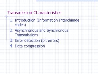
[ ] ] [ 1 1 1 0 1 0 0 0 1 1 1 0 1 0 1 1 0 1 0 0 1 0 0 0 1 0 0 1 0 0 1 0 0 1 0 0 0 0 1 1 1 1 1 1 0 1 0 1 1 H= G= Block Code • Data is matrix multiplied* by a pre-defined matrix to generate parity check bits, which are appended to data and then transmitted • Hamming code example: Matrix multiply* a 4-bit code value by this 7,4 matrix G to produce a 7 bit message. Any 1 bit error position will be indicated by matrix multiplication of the received 7 bit value with the matrix H. The three bits of the result, if non-zero, are the binary value of the position of the single bit error. • more than 1 bit error is detected but not correctable • To “matrix multiply” a 4 bit binary code by the G matrix, compute 7 different bit values. The first bit is found by first multiplying* each of the 4 data bits respectively by the four bits in the first row, and then adding* the four products. The second bit is computed the same way, using the second row of G, and so on. * Ring sum or modulo 2 32
Encryption • In many circumstances, communication signals are physically accessible to unauthorized persons • Particularly in cellular and PCS radio, microwave radio, and in some wire transmission systems • Encryption (a reversible modification of the information, before transmission via the non-secure environment) is becoming much more important for the general telecommunication user in contrast to previous use mainly for military and diplomatic communication • Most authentication algorithms depend upon the person (or equipment) in question using an encryption “key” value, known only to authorized persons, in an encryption process to prove they are the authentic source of certain information • Here are a few significant facts about encryption:
Vernam and Vignière • Gilbert S. Vernam, an AT&T engineer working with teletypewriters during WW I, developed the modern binary encryption method called a running binary mask (or key) cipher • A random-appearing binary bit stream is “added*” to the transmitted binary bit stream data before transmission in an non-secure environment. *Addition is modulo-2, or XOR. • A duplicate properly synchronized random- appearing bit stream is “subtracted*” modulo-2 from the received bit stream, in a secure environment. • This is a binary version of an earlier alphabetic cipher method invented in the 17th century by the French diplomat, Vignière
GSM Radio Encryption encryption mask from algorithm A8 Representative cellular/PCS encryption process replica of original information Um radio interface XOR XOR information bits. Certain data bits used for synchronization, etc., are not encrypted. Locally generated and properly synchronized copy of encryption mask, also generated by algorithm A8 11001100 information bits +10101010 mask 01100110 result seen at Um +10101010 mask again 11001100 info restored Note that there is no “carry” done with the XOR binary “addition” example. 35
The Difficult and Nice Parts Difficult things to do: • Producing a running mask binary bit pattern which cannot be calculated or discovered by an interceptor (the “enemy” or the “competition”) because it appears to be random, not periodic • Maintain proper synchronization between the running mask at the transmitter and the receiver Nice properties: • A single bit error in the transmission channel produces only a single bit error in the result • Unlike “block” ciphers (example: NIST Data Encryption Standard), which produces errors in all the bits in a block of 64 due to one channel bit error.
Public Policy Issues • The US, Canadian, British and some other governments have already legally restricted the use of encryption to some degree • US, Canadian export of encryption technology is restricted • Divergent objectives of private manufacturers of encryption equipment vs. government desire to keep strong encryption technology out of the hands of enemy states, criminals or other undesirable users, have produced conflict. US government desires to restrict the sale and use of encryption domestically, and require only encryption methods which have “escrow” storage of secret keys, accessible to law enforcement agencies under a court order. • Attempt to compel use of a government devised “Clipper” encryption chip was abandoned after flaws in its design were discovered. Many observers also objected to this for other reasons as well.
Recent Government Policy Shift • In 1999, the US Government agreed for the first time to allow export of cryptographic technology which uses long secret keys (more than 128 binary bits.) • Length of the key is significant, because this controls the quantity of different key values that must be evaluated when using a powerful computer as a “brute force” tool to determine the correct key. • Previous US-Canada policy usually blocked cryptography export under ITAR (International Trade in Arms Restriction) laws. • Critics pointed out that non-US suppliers of cryptography had good products too, and were not prevented from selling world wide! • FBI and other police organizations still want a “back door” to commercial encryption processes under court order to defeat criminal users. • An important topic where technology and public policy intersect.
Farewell! • This completes the prepared lectures in this course. • I hope that this gave you an understanding of how the technology underlying various telecommunications systems works • The purpose of your term paper is to give you more practice in researching a topic of interest to yourself and learning more about it. • Please stay in touch if you have questions or comments at any time in the future.