Download
1 / 47
480 likes | 741 Vues
Introduction to Database Design. Entity Relationship Model. Design of a Database. Design phases: Requirement Analysis Talk to people and figure out what they want Conceptual Database Design Do the design Many tools/modeling techniques ER , UML , Rambaugh, Booch, Yordon

E N D
Introduction to Database Design Entity Relationship Model
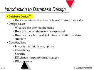
Design of a Database • Design phases: • Requirement Analysis • Talk to people and figure out what they want • Conceptual Database Design • Do the design • Many tools/modeling techniques • ER, UML, Rambaugh, Booch, Yordon • Logical Database Design • Actual database tables in relational model, or OO model or XML model • Here – only relational model.
Overview of Database Design • Conceptual design: (ER Model is used at this stage.) • What are the entities and relationships in the enterprise? • What information about these entities and relationships should we store in the database? • What are the integrity constraints or business rules that hold? • A database `schema’ in the ER Model can be represented pictorially (ER diagrams). • Can map an ER diagram into a relational schema.
Entity-Relationship Model • Entity Sets • Relationship Sets • Mapping Constraints • Keys • E-R Diagram • Extended E-R Features • Design Issues • Design of an E-R Database Schema • Reduction of an E-R Schema to Tables
Entity Sets • A database can be modeled as: • a collection of entities, • relationship among entities. • An entity is an object that exists and is distinguishable from other objects. Example: specific person, company, event, plant • Entities are described using attributesExample: people have names and addresses • An entityset is a set of entities of the same type that share the same properties. Example: set of all persons, companies, trees, holidays
Entity Sets customer and loan customer-id customer- customer- customer- loan- amount name street city number
Attributes • An entity is represented by a set of attributes, that is descriptive properties possessed by all members of an entity set. Example: customer = (customer-id, customer-name, customer-street, customer-city) loan = (loan-number, amount) • Domain – the set of permitted values for each attribute • Keys: Minimal set of attributes whose values uniquely identify an entity in the set • Candidate Keys: all sets of attributes that can potentially be a key. • Primary Key: One of the candidate keys is chosen to be a “primary” key.
Relationship Sets • A relationship is an association among several entities Example:Hayes depositorA-102customer entity relationship set account entity • A relationship set is a mathematical relation among n 2 entities, each taken from entity sets {(e1, e2, … en) | e1 E1, e2 E2, …, en En}where (e1, e2, …, en) is a relationship • Example: (Hayes, A-102) depositor • There can be multiple relationship sets between the same two entities. • A relationship must be uniquely identified by the participating entities.
Descriptive Attributes • Descriptive attributes: used to record information about the relationship • When was the last time that the customeraccessed his/her account.
E-R Diagrams • Rectangles represent entity sets. • Diamonds represent relationship sets. • Lines link attributes to entity sets and entity sets to relationship sets. • Ellipses represent attributes • Underline indicates primary key attributes (coming up)
Ternary Relationships • Ternary relationships - used to record associations between three entity sets. • Example: Each branch has several jobs that can be worked on by • For this we need to record the association between employees, branches and jobs.
Roles/Self Referential Relationships • Entity sets of a relationship need not be distinct • The labels “manager” and “worker” are called roles; they specify how employee entities interact via the works-for relationship set. • Roles are indicated in E-R diagrams by labeling the lines that connect diamonds to rectangles. • Role labels are optional, and are used to clarify semantics of the relationship
Constraints in ER • Key Constraints • Cardinality Constraints • Participation Constraints • Overlapping Constraints (ISA) • Coverage Constraints (ISA)
Key Constraints • Consider depositor relationship: A customer can deposit into many accounts; an account can have many depositors. • Compare with: Each department has at most one Manager Contrast with: Each customer can be the borrower on one loan. However, each loan can have many borrowers. The restriction that each customer can be borrower on one loan => Key Constraint
Key Constraint II • Relationship set like borrower - sometimes said to be one-to-many • Relationship set between customers and accounts -> many-to-many
Key Constraint III • Additional Restriction: a loan may be borrowed by only one customer -> one-to-one • Textbook clarification: arrow shown to go from customer to borrower • Means same thing! • Implies that customer entity participates in the borrower relationship set only once.
Key Constraints for Ternary Relationships • Key constraints in binary relationships can be easily extended to ternary.
Alternative Notation for Cardinality Limits • Cardinality limits can also express participation constraints
Participation Constraints • Totalparticipation (indicated by double/thick line): every entity in the entity set participates in at least one relationship in the relationship set • E.g. participation of loan in borrower is total • every loan must have a customer associated to it via borrower • Partial participation: some entities may not participate in any relationship in the relationship set • E.g. participation of customer in borrower is partial • Not every customer has a loan
Keys • A super key of an entity set is a set of one or more attributes whose values uniquely determine each entity. • A candidate key of an entity set is a minimal super key • Customer-id is candidate key of customer • account-number is candidate key of account • Although several candidate keys may exist, one of the candidate keys is selected to be the primary key.
Weak Entity Sets • Assumption so far: • Attributes associated with an entity contain a key (to uniquely identify the entities) • Not always the case! • Example: • Employees can purchase policies to cover their dependents. • We need to record information about policies: • Who is covered, Who owns the policy • Don’t really care about the dependents beyond that • If employee quits, policy is deleted and coverage for dependents stopped! • This above is modeled via a Weak Entity Set. • An entity set that does not have a primary key is referred to as a weak entity set. • Weak entity is uniquely identified by a conjunction of some of its attributes and the primary key of another entity - Identifying entityset
Weak Entity Sets • Restrictions: • it must relate to the identifying entity set via a one-to-many relationship set from the identifying to the weak entity set • It must have total participation in the identifying relationship set.
Weak Entity Sets (Cont.) • We depict a weak entity set by double rectangles. • We underline the discriminator of a weak entity set with a dashed line. • payment-number – discriminator of the payment entity set • Primary key for payment – (loan-number, payment-number)
Conceptual Design Using the ER Model • Design choices: • Should a concept be modeled as an entity or an attribute? • Should a concept be modeled as an entity or a relationship? • Identifying relationships: Binary or ternary? Aggregation? • Constraints in the ER Model: • A lot of data semantics can (and should) be captured. • But some constraints cannot be captured in ER diagrams. • Constraints on individual attributes of an entity • Employee enitites must have age > 24
Entity vs. Attribute • Remember – attribute values are atomic (cannot be broken down further) • Should addressbe an attribute of Employees or an entity (connected to Employees by a relationship)? • Depends upon the use of address information, and the semantics of the data: • If we have several addresses per employee, address must be an entity (since attributes cannot be set-valued). • If address is to be shared by many employees, address should be an entity. • If the structure (city, street, etc.) is important, e.g., we want to retrieve employees in a given city, address must be modeled as an entity (since attribute values are atomic).
to from name dname did ssn lot budget Departments Works_In2 Employees name dname ssn lot did budget Works_In3 Departments Employees Duration to from Entity vs. Attribute (Contd.) • Works_In2 does not allow an employee to work in a department for two or more periods. • Similar to the problem of wanting to record several addresses for an employee: we want to record several values of the descriptive attributes for each instance of this relationship.
since dbudget name dname ssn lot did budget Departments Employees Manages2 name dname ssn lot did budget Departments Manages3 Employees since Mgr_Appts apptnum dbudget Entity vs. Relationship • First ER diagram OK if a manager gets a separate discretionary budget for each dept. • What if a manager gets a discretionary budget that covers all managed depts? • Redundancy of dbudget, which is stored for each dept managed by the manager. - Misleading: suggests dbudget tied to managed dept.
name ssn pname lot age Dependents Employees Covers Policies policyid cost name pname age ssn lot Dependents Employees Purchaser Beneficiary Policies policyid cost Binary vs. Ternary Relationships • Consider Figure 1 - What does it depict? • Additional constraints: • A policy cannot be owned jointly by two employees • Every policy must be owned by some employee • Dependents is a weak entity set - uniquely identified by policyId
Binary vs Ternary • Constraint 1: Add a key constraint on Policies with respect to Covers • Side effect: policy can cover only one dependent • Constraint 2: Total participation constraint on Policies • Ok if each policy covers at least one dependent • Constraint 3: Introduce an indentifying relationship set
name ssn pname lot age Dependents Employees Covers Policies policyid cost name pname age ssn lot Dependents Employees Purchaser Beneficiary Policies policyid cost Better Solution
Are you awake? ER Group Exercise
Class (ISA) Hierarchies • As in C++ or Java, attributes are inherited • If we declare A ISA B, every A entity is also considered to be a B entity.
ISA Hierarchy Constraints • Overlap Constraints: Can Joe be both an employee and a customer? (Allowed/Disallowed) • Does every employee entity also have to be an officer or teller or secretary entity? (Yes/No) • Reasons for using ISA: • To add attributes specific to a subclass • To identify entities that participate in a relationship
Employees name Aggregation ssn lot • Used when we have to model a relationship involving (entitity sets and) a relationship set. • Aggregation allows us to treat a relationship set as an entity set for purposes of participation in (other) relationships. Monitors until since started_on dname pid pbudget did budget Sponsors Departments Projects • Aggregation vs. ternary relationship: • Monitors is a distinct relationship, • with a descriptive attribute. • Also, can say that each sponsorship • is monitored by at most one employee.
Case Study (from Text Book) • See Handout • Addition to earlier exercise.
Summary of Conceptual Design • Conceptual design follows requirements analysis, • Yields a high-level description of data to be stored • ER model popular for conceptual design • Constructs are expressive, close to the way people think about their applications. • Basic constructs: entities, relationships, and attributes (of entities and relationships). • Some additional constructs: weak entities, ISA hierarchies, and aggregation. • Note: There are many variations on ER model.
Summary of ER (Contd.) • Several kinds of integrity constraints can be expressed in the ER model: key constraints, participationconstraints, and overlap/covering constraints for ISA hierarchies. Some foreign key constraints are also implicit in the definition of a relationship set. • Some constraints (notably, functional dependencies) cannot be expressed in the ER model. • Constraints play an important role in determining the best database design for an enterprise.
Summary of ER (Contd.) • ER design is subjective. There are often many ways to model a given scenario! Analyzing alternatives can be tricky, especially for a large enterprise. Common choices include: • Entity vs. attribute, entity vs. relationship, binary or n-ary relationship, whether or not to use ISA hierarchies, and whether or not to use aggregation. • Ensuring good database design: resulting relational schema should be analyzed and refined further. FD information and normalization techniques are especially useful.
UML • UML: Unified Modeling Language • UML has many components to graphically model different aspects of an entire software system • UML Class Diagrams correspond to E-R Diagram, but several differences.
UML Class Diagrams (Contd.) • Entity sets are shown as boxes, and attributes are shown within the box, rather than as separate ellipses in E-R diagrams. • Binary relationship sets are represented in UML by just drawing a line connecting the entity sets. The relationship set name is written adjacent to the line. • The role played by an entity set in a relationship set may also be specified by writing the role name on the line, adjacent to the entity set. • The relationship set name may alternatively be written in a box, along with attributes of the relationship set, and the box is connected, using a dotted line, to the line depicting the relationship set. • Non-binary relationships cannot be directly represented in UML -- they have to be converted to binary relationships.
UML Class Diagram Notation (Cont.) *Note reversal of position in cardinality constraint depiction
Cardinality constraints are specified in the form l..h, where l denotes the minimum and h the maximum number of relationships an entity can participate in. Beware: the positioning of the constraints is exactly the reverse of the positioning of constraints in E-R diagrams. The constraint 0..* on the E2side and 0..1 on the E1 side means that each E2 entity can participate in at most one relationship, whereas each E1 entity can participate in many relationships; in other words, the relationship is many to one from E2 to E1. Single values, such as 1 or * may be written on edges; The single value 1 on an edge is treated as equivalent to 1..1, while * is equivalent to 0..*. UML Class Diagrams (Contd.)