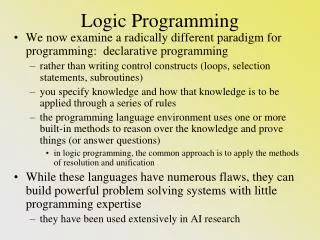
Sensors and Programming Logic
230 likes | 384 Vues
Sensors and Programming Logic. David Dominguez. Goals and Objective. Build an understanding of The Systems Engineering Process Robot Design Sensors and instruments Example Scenario Programming Logic. The Systems Engineering Process.

Sensors and Programming Logic
E N D
Presentation Transcript
Sensors and Programming Logic David Dominguez
Goals and Objective • Build an understanding of • The Systems Engineering Process • Robot Design • Sensors and instruments • Example Scenario • Programming Logic
The Systems Engineering Process • An iterative** process that translates simply-stated needs into complex systems • Phases of systems engineering process • Define mission requirements and constraints • Derive system requirements and constraints • Design subsystems • Loops** of systems engineering process • Requirements loop: Verify derived requirements match overall mission requirements and constraints • Design loop: Verify subsystem designs meet system requirements and constraints • Validation loop: Verify the overall system design meets mission requirements and constraints (Sellers, 2005)
Systems Engineering “V” Top-down design, bottom-up realization (DOT diagram)
Robot Design • Be mindful of mass properties • Weight & Balance • Size, length of arm, etc. • Design for stability • Divide and Conquer • Break complex tasks into smaller easier to solve sub-problems. • Use CAD to model your game field and your robot. • Maintain documentation even if your ideas failed. Lesson Learned
Sensors and Instruments • An instrument reads signals converted by a sensor • Voltmeter reads the output of a thermocouple • Thermometer reads the displacement of mercury • A sensor is a device that measures a physical quantity and converts it into a signal which can be observed by an instrument • Thermocouple converts changes in temperature into voltage • Potentiometer • Infrared (IR) sensor • Ultrasonic range finder, etc.
General Sensors • IR sensors • With programming logic you can differentiate colors to follow specific lines, determine size, shape and range of surrounding objects • Ultrasonic Range Finder • Uses sound to determine range and size of surrounding objects • Light Sensor • Photocell that senses light • Optical Shaft Encoders • Uses optics to measure both the position and direction of rotation of a shaft (radial/angular movement) • Potentiometers • Variable resistance for voltage gain control • Also useful to determine position and direction of radial angles • Can be used to calculate displacement velocity and acceleration • Accelerometer • Detects acceleration • Allows you determine direction, velocity and displacement of a robot
Robotics Example using a Potentiometer to solve a problem • Scenario • Semiconductor manufacturer needs a robot to load and unload the Applied Materials Centura Avatar Etch machines in a cleanroom • Deliver the etched wafer to wafer inspection machines located at the end of the robots track • Reverse direction and repeating the same tasks in reverse • Repeat • Define Requirements and constraints
Cleanroom Scenario Datum 15m 3m 3m Wheel has a circumference of 50cm c = π(dia.) • 1 Motor: Reversible, -100 to 100 proportional output range • 1 Potentiometer: Operating range of 0o-10800o • 1 rail mounted wheel 50cm in circumference, direct drive to motor& potentiometer • At |100| robot velocity = 2m/sec • 1 rev=360o=50cm of displacement; or 0.5m per revolution
Question and Answer • Q: How do we determine robot position in cm and/or m?
Question and Answer • Q: How do we determine robot position in inches and feet? • A: Read the potentiometer value and apply math.
Question and Answer • Q: How do we determine robot position in inches and feet? • A: Read the potentiometer value and apply math. • Example: • Pval= 3894o; c=50cm; 360o per revolution • Displacement, d=number_of_revs * c • number_of_revs = Pval/360o • d=3894o/360o(50cm)=540.83cm or 5.4083m from datum
Review of Position and its Derivatives • Velocity; v = d/t; more accurately v→=Δd/Δt • Acceleration; a→=Δv/Δt; units d/s2 or d s-2 • Jerk; j→=Δa/Δt; units d/s3 or d s-3 • Jounce aka snap; s→=Δj/Δt; units d/s4 or d s-4
Cleanroom Scenario Datum 15m 3m 3m • Beginning velocity = 0 • Robot accelerates to max velocity at midway (1.5m) point between machines. • Robot decelerates to 0 at 3m and changes wafer cartridge • Repeat until the end where robot places etched wafers in the inspection bin • Reverses track and repeat the tasks depositing etched wafers at bin on opposite side
Proportional-Integral-Derivative (PID) Theory Manipulated Variable (MV) Setpoint(SP) Process Variable (PV) (Wikipedia Image)
PID Control • A PID controller • reads a sensor • computes the desired actuator output by calculating proportional, integral, and derivative responses • summing the three components to compute the output • Proportional depends on the the difference between the set point and the process variable (present error) • Integral component sums the error term over time • Derivative response is proportional to the rate of change of the process variable. It is a prediction of future errors, based on current rate of change. (National Instruments, 2011)
Sample Motor Response Shows the step input and the motor response using a time constant value of t0 = 0.2s. The response of the motor starts out slowly due to the time constant, but once that is out of the way the motor position ramps at a constant velocity. (Wescott, 2000)
PID (proportional) Interrupt Service Routine Set Point SP Manipulated Variable MV Proportional Gain Constant Process Variable PV
PID (proportional) Interrupt Service Routine (EasyC Sample Project files)
PID (proportional) Interrupt Service Routine Continued (EasyC Sample Project files)
Control Loop for PID using Potentiometer SP PV MV (EasyC Sample Project files)
References • Sellers, J. J. (2005). Understanding Space: An Introduction to Astronautics (3rd ed.). New York, NY: McGraw Hill. • Easy C Documentation and Sample Project Files • National Instruments Tutorial (2011). PID Theory Explained, http://www.ni.com/white-paper/3782/en#toc2 • Wescott, Tim, FLIR Systems (2000). PID Control: PID Without a PhD. EE Times-India, http://www.google.com/url?sa=t&rct=j&q=pid%20without%20a%20phd&source=web&cd=1&ved=0CFkQFjAA&url=http%3A%2F%2Figor.chudov.com%2Fmanuals%2FServo-Tuning%2FPID-without-a-PhD.pdf&ei=_VgYUI-lHIXW9QT29IHABw&usg=AFQjCNFWS6tbKLEO6qRCncHB2m6ZBbqtuw&cad=rja