Download
1 / 33
330 likes | 505 Vues
SABR SUBCRITICAL ADVANCED BURNER REACTOR. W. M. STACEY Georgia Tech October, 2007. ACKNOWLEDGEMENT.

E N D
SABRSUBCRITICAL ADVANCED BURNER REACTOR W. M. STACEY Georgia Tech October, 2007
ACKNOWLEDGEMENT SABR is the sixth in a series of fast transmutation reactor concepts that have been developed in faculty-student design projects at Georgia Tech. The contributions of E. Hoffman, R. Johnson, J. Lackey, J. Mandrekas, C. De Oliviera, W. Van Rooijen, D. Tedder and numerous students in the Nuclear & Radiological Engineering Design classes is gratefully acknowledged. Subcritical Advanced Burner Reactor
Motivation ● GNEP calls for building pure TRU-fuel ‘Advanced Burner Reactors’ (ABRs) to fission the Transuranics (TRU) in spent nuclear fuel ● Pure TRU-fuel transmutation reactors present safety & fuel cycle challenges that can be met by sub-critical operation SMALLER β: operating sub-critical, , increases margin to prompt critical from to , which more than compensates for the much smaller delayed neutron fraction, , for TRU than for U235. SMALLER DOPPLER: added margin to prompt critical with subcritical operation in part compensates the very small, probably positive, fuel Doppler temperature coefficient of reactivity in the absence of U238 in pure TRU fuel. LARGER BURNUP ρ Decrement: neutron source strength can be increased to offset large burnup reactivity decrement of pure TRU fuel (No U238), greatly increasing achievable TRU burnup per burn cycle Subcritical Advanced Burner Reactor
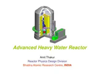
Annular Core Metal TRU-ZR Fuel Sodium Cooled ODS Structure 3000 MWt FAST REACTOR 4-batch Fuel Cycle PYRO-processing > 90% Burnup of TRU 200 MWt TOKAMAK Neutron Source Based on ITER Physics & Technology Tritium Self-sufficient Operational 2035-40 Subcritical Advanced Burner Reactor
LiNbO3 t=0.3 mm Fuel R=2 mm ODS Clad t=0.5 mm Na Gap t=0.83 mm FUEL Axial View of Fuel Pin Composition 40Zr-10Am-10Np-40Pu (w/o) (Under development at ANL) Design Parameters of Fuel Pin and Assembly Cross-Sectional View Fuel Assembly Subcritical Advanced Burner Reactor
Fuel Fabrication Facility (Based on ongoing ANL R&D) • Assuming downtime of 33%, one facility could produce rods containing 8,760 kg TRU/yr • The initial fuel loading for SABR (4 batches) requires 35,996 kg TRU • To fabricate the initial fuel loading would require either 4 years - using 1 fabrication facility, • or 1 year - using 4 facilities Subcritical Advanced Burner Reactor
Neutronics CODES EVENT Multigroup, 2D Spherical Harmonics (238 and 27 GRPS) MCNP Continuous Energy Monte Carlo CSAS Calculates Event X-SECTS NJOY Doppler Broaden ENDF/B-VI.6 and –VII Libraries SCALE/ORIGEN Isotopic Burnup 4-Batch Layout of Fuel Assemblies Initial Loading of 36 MT of Fresh TRU Yields Keff = 0.95. 16 B4C Control Assemblies Worth 9$. Subcritical Advanced Burner Reactor
R-Z Cross section SABR calculation model Subcritical Advanced Burner Reactor
4-BATCH FUEL CYCLE TRU FUEL COMPOSITION • 4 750-d burn cycles • 3000 d (8.2 yr) total residence • keff = 0.95 fresh TRU (BOL) • keff = 0.89 (BOC) to 0.83 (EOC) • Pfus(MW)= 99 (BOC) to 164 (EOC) • 25% TRU burnup per 4-batch burn cycle, >90% with repeated recycling • Pfis = 3000MWt transmutes 1.06 MT TRU/FPY • 1000 MWe LWR produces 0.2 MT TRU/yr • Fuel cycle constrained by 200 dpa (8.4 FPY) clad radiation damage lifetime. ANNULAR CORE CONFIGURATION Subcritical Advanced Burner Reactor
Doppler Coefficient vs Average Fuel Temperature Subcritical Advanced Burner Reactor
Sodium Voiding Reactivity Subcritical Advanced Burner Reactor
Fuel Pin Analysis • Fuel pin designed to a clad radiation damage lifetime of 200 dpa. At fast neutron fluence of 6.23x10²² n/cm2 per FPY (23.7 dpa/FPY), radiation damage lifetime is 8.44 FPY. • Fuel plenum designed to withstand gas pressure buildup for 8.44 FPY and not exceed creep strain limit of 1%. Based on ORIGEN calculation of gas buildup, the pressure at 8.44 FPY will be 11.1 MPa, for which the creep strain < 1%. • Cumulative Damage Fraction analysis indicates that the mean time to rupture is much greater than the actual time of the pin in the core throughout the fuel cycle. Subcritical Advanced Burner Reactor
Salt Metal Fabrication of New Fuel Oxide Reduction Electrorefiner TRUs + salt LWR Spent Fuel Oxide Metal Cathode Processor Cladding + Fission Products Salt Zeolite + fission products Zeolite Columns Melting Furnace Furnace Ceramic Waste WaWasteWaste High Level Waste Metal Waste Flowchart of Pyroprocessing Facilities (ADAPTED FROM ONGOING ANL R&D) RECOVERY RATES: Pu and Np 99.85%, Am 99.97% and Cm 99.95%. Subcritical Advanced Burner Reactor
Core Thermal Analysis Temperature Distribution in Fuel Pin (fuel 0.0-0.2cm, Na-gap 0.2-0.28cm, clad 0.28-0.33cm, LiNbO3 0.33-0.36cm) Subcritical Advanced Burner Reactor
Core Thermal Analysis (cont.) Core Thermal and Heat Removal Parameters In the absence of a lithium niobate electrically insulating coating on all metallic surfaces in the fuel assemblies, an MHD pressure drop of 68 MPa would be generated, requiring a pumping power of 847 MW. Subcritical Advanced Burner Reactor
Core Heat Removal and Power Conversion Heat Removal and Power Generation Cycle Primary and intermediate Na loops Secondary water Rankine cycle THERMAL POWER GENERATED 3000 MWt ELECTRICAL POWER PRODUCED 1049 MWe ELECTRICAL POWER USED 128 MWe NET ELECTRICAL POWER 921 MWe ELECTRICAL CONVERSION EFFICIENCY 30.7 % Subcritical Advanced Burner Reactor
Relationship Between Fusion Power and Reactor k The multiplication constant of the fissionable fuel, k, decreases with fuel burnup, but the fusion neutron source (power) can be increased with TRU burnup to compensate reduction in k. Thus, the maximum Pfus determines the minimum k for which the reactor can maintain a given fission power output, hence the TRU burnup in a fuel cycle. EQUILIBRIUM FUEL CYCLE PARAMETERS FOR Pfis = 3000 MWt *depends on spectrum and material. Subcritical Advanced Burner Reactor
Neutron Source Design Parameters Physics (stability, confinement, etc), Engineering (stress, radiation protection, etc) and Radial Build Constraints determine allowable design space. The design parameters for a Tokamak neutron source for transmutation are similar to those for ITER. Operation of ITER will serve as a prototype for a Tokamak fusion neutron source Subcritical Advanced Burner Reactor
Neutron Source Design Parameters(cont.) SABR TOKAMAK NEUTRON SOURCE PARAMETERS *May Require Extension Beyond ITER ***Definitely Requires Extension Beyond ITER Subcritical Advanced Burner Reactor
400-500 MW Operation Space at 10 MA Operational space of SABR at 10 MA14 (Horizontal lines indicate Pfus and slanted lines Paux) There is a broad range of operating parameters that would achieve the 10 MA, 400-500 MW operating point. Subcritical Advanced Burner Reactor
150-200 MW Operating Space Physics (stability, confinement, etc) and Radial Build Constraints determine operating space. POPCON for SABR reference design parameters (I =7.2MA) There is a broad operating parameter range for achieving the nominal design objective of Pfus = 150-200 MW. Subcritical Advanced Burner Reactor
Heat Removal from Fusion Neutron Source -- Design for 500 MWt plasma -- 50%/50% first wall/divertor -- ITER designs adapted for Na -- FLUENT/GAMBIT calculations Subcritical Advanced Burner Reactor
Heat Removal from Fusion Neutron Source (cont.) First Wall • Be coated ODS (3.5 cm plasma to Na) • Design peak heat flux 0.5-1.0 MW/m2 • Nominal peak heat flux 0.25 MW/m2 • Temperature range 600-700 C (1200 C max) • Tin = 293 C, Tout = 600 C • Coolant mass flow 0.06 kg/s • 4x10²² (n/cm2)/FPY = 33 dpa/FPY • Radiation damage life 200 dpa = 8.1 yr @ 500 MW & 75% 20.2 yr @ 200 MW & 75% Divertor Module • Cubic W (10mm) bonded to CuCrZr • Na in same ITER coolant channels • Design Peak heat flux 1 – 8 MW/m2 (ITER < 10 MW/m2) • Tin = 293 C, Tout = 756 C • Coolant mass flow 0.09 kg/s • Lifetime - erosion Subcritical Advanced Burner Reactor
Li4SiO4 Tritium Breeding Blanket 15 cm Thick Blanket Around Plasma (Natural LI) and Reactor Core (90% Enriched LI) Achieves TBR = 1.16. NA-Cooled to Operate in the Temperature Window 420-640 C. Online Tritium Removal by He Purge Gas System. Dynamic Tritium Inventory Calculations for 750 d Burn Cycle Indicated More Than Adequate Tritium Production. Subcritical Advanced Burner Reactor
section between TFC magnets 0.6 m2 LH Launchers, 20 MW Power Input, 1.5 MA Current Drive for each SABR Lower Hybrid Heating & CD System 2 SETS of 3 PORTS @ 180o 20 MW Per 0.6 m2 PORT H&CD SYSTEM PROPERTIES ** 4 equatorial, 3 upper, 3 NBI, ** ICRH power density Used ITER LH Launcher Design Subcritical Advanced Burner Reactor
SABR S/C Magnet Design Adapted from ITER Detailed cross section of CS cable-in-conduit conductor Subcritical Advanced Burner Reactor
SABR S/C Magnet Design Adapted from ITER (cont.) TF coil parameters Central Solenoid Parameters Subcritical Advanced Burner Reactor
SHIELD Shield Layers and Compositions SHIELD DESIGNED TO PROTECT MAGNETS MAX FAST NEUTRON FLUENCE TO S/C = 1019 n/cm2 MAX ABSORBED DOSE TO INSULATOR 109 /1010 RADS (ORG/CER) CALCULATED IRRADIATION IN 40 YEARS AT PFUS = 500 MW AND 75% AVAILABILITY FAST NEUTRON FLUENCE TO S/C = 6.9x10¹⁸ n/cm2 ABSORBED DOSE TO INSULATOR = 7.2 x 10⁷ RADS Subcritical Advanced Burner Reactor
Dynamic Analysis of Loss of Flow Subcritical Advanced Burner Reactor
Dynamic Analysis of Loss of Flow (cont.) THE SUBCRITICAL REACTIVITY MARGIN PROVIDES 10’S SECONDS FOR CORRECTIVE CONTROL ACTION. Subcritical Advanced Burner Reactor
SUMMARY & CONCLUSIONS • The GNEP concept of a pure TRU-fuel burner reactor is challenging because of large burnup reactivity decrement, small delayed neutron fraction and small Doppler coefficient in the absence of U238. • SABR, a subcritical, TRU-ZR fuel, NA-cooled fast reactor design concept has been developed, based on current nuclear technology R&D. • A Tokamak DT fusion neutron source, based on ITER physics and technology, has been shown to be adequate to support the subcritical reactor. • Fuel residence time in SABR is limited by clad failure at 200 dpa to 8.4 FPY. • a 4-batch, 8.2 FPY fuel cycle burns 25% of the TRU fuel in SABR, with keff =0.83 and Pfus = 164 MWt at EOC. • > 90% burnup can be achieved in SABR by repeated recycling, with reprocessing. • Dynamic analysis of loss-of-flow accident indicates that the SABR sub-criticality margin provides 10’s of seconds to initiate control action. Subcritical Advanced Burner Reactor