Download
1 / 43
430 likes | 466 Vues
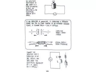
Dive into the world of induction and inductors, including Faraday’s Law, coil discussions, calculations, and circuit analysis from the Fall 2006 class. Explore the impact of changing magnetic fields, induced EMF, and current flow in coils and circuits.

E N D
Induction -->Inductors Back to Circuits for a bit …. Induction - Fall 2006
What the heck are we doing? • Today • 7:30 AM we had our problem review session • Continue on with Induction & Inductors • Watch those piling up WebAssigns! • Monday • More of the same, • Wednesday • EXAMINATION #3 • After Holiday • Complete the remaining six chapters in the syllabus. Induction - Fall 2006
The loop is pushed into a region where the magnetic field is into the page. The motion creates an induced current in the loop which in turn produces a magnetic field at A and B. • The field at A & B are the same. • The field at A is stronger than the one at B • The field at B is stronger than the one at A. • None of these. Induction - Fall 2006
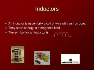
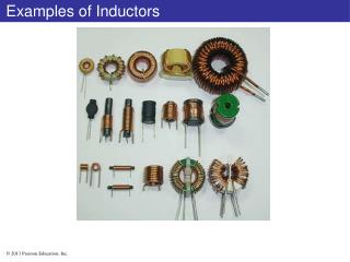
Today we will consider a Coil Induction - Fall 2006
We will base our discussion on Faraday’s Law Lentz Induction - Fall 2006
Consider the following: • There are N turns in the solenoid. • There is a current flowing in the direction shown. • The power supply is set to 20 volts and the resistor is 10 ohms. • The coil wire has negligible resistance. Induction - Fall 2006
The steady state current (20 volts, 10 ohms) in the circuit is • 2 amperes • Less than 2 amperes • More than 2 amperes • Need more info. Induction - Fall 2006
A B The DIRECTION of the magnetic field in the coil is • From A to B • From B to A • Not enough information is given. Induction - Fall 2006
Back to the coil diagram … • Recall from the last discussion that the magnetic field in the coil is given by: • n = #turns per unit length • Coil is infinitely long • Sort of B Induction - Fall 2006
B Back to the coil diagram … • The Flux through a single turn of the coil is BA or m0niA. • Now, let’s increase the applied voltage linearly at a rate of DV/Dt. • The current will change at a rate DI/Dt. Induction - Fall 2006
B Back to the coil diagram … For the single coil (as Dt0) FARADAY Says: Induction - Fall 2006
B Looking into the coil from the end with the red arrow, the emf around the coil inducedcurrent will be • In a clockwise direction • In a counterclockwise direction Induction - Fall 2006
B So … the induced emf • Will create a current that will oppose the change in the current. • The induced emf will therefore oppose the applied voltage (also an emf) from the power supply. Induction - Fall 2006
So for the single coil Induction - Fall 2006
Definition of Inductance L UNIT of Inductance = 1 henry = 1 T- m2/A FB is the flux near the center of one of the coils making the inductor Induction - Fall 2006
An inductor in the form of a solenoid contains 420 turns, is 16.0 cm in length, and has a cross-sectional area of 3.00 cm2. What uniform rate of decrease of current through the inductor induces an emf of 175 μV? Induction - Fall 2006
Look at the following circuit: • Switch is open • NO current flows in the circuit. • All is at peace! Let's close the switch.... Induction - Fall 2006
At the INSTANT that the switch is closed, the current through the resistor is: • Zero • E/R • Can’t tell Induction - Fall 2006
Three years after the switch is closed, the current through the resistor is: • E/R • Zero • Don’t care .. we will be out by then! Induction - Fall 2006
Graph? IR E/R Probably looks something Like this. time Induction - Fall 2006
Close the circuit… • After the circuit has been closed for a long time, the current settles down. • Since the current is constant, the flux through the coil is constant and there is no Emf. • Current is simply E/R (Ohm’s Law) Induction - Fall 2006
Close the circuit… • When switch is first closed, current begins to flow rapidly. • The flux through the inductor changes rapidly. • An emf is created in the coil that opposes the increase in current. • The net potential difference across the resistor is the battery emf opposed by the emf of the coil. Induction - Fall 2006
Looking at the math Induction - Fall 2006
Just as we did with the capacitor, we can solve this equation and we get: Induction - Fall 2006
The growth Induction - Fall 2006
Death of the current: Induction - Fall 2006
Graph Induction - Fall 2006
Consider the Solenoid Again… l n turns per unit length Induction - Fall 2006
Inductance & Geometry Depends only on geometry just like C and is independent of current. Induction - Fall 2006
Max Current Rate of increase = max emf VR=iR ~current Induction - Fall 2006
Solve the loop equation. Induction - Fall 2006
IMPORTANT QUESTION • Switch closes. • No emf • Current flows for a while • It flows through R • Energy is conserved (i2R) WHERE DOES THE ENERGY COME FROM?? Induction - Fall 2006
E=e0A/d +dq +q -q For an answerReturn to the Big C • We move a charge dq from the (-) plate to the (+) one. • The (-) plate becomes more (-) • The (+) plate becomes more (+). • dW=Fd=dq x E x d Induction - Fall 2006
The calc The energy is in the FIELD !!! Induction - Fall 2006
What about POWER?? power to circuit power dissipated by resistor Must be dWL/dt Induction - Fall 2006
So Energy stored in the Capacitor Induction - Fall 2006
WHERE is the energy?? l Induction - Fall 2006
Remember the Inductor?? ????????????? Induction - Fall 2006
So … Induction - Fall 2006
ENERGY IN THEFIELD TOO! Induction - Fall 2006
IMPORTANT CONCLUSION • A region of space that contains either a magnetic or an electric field contains electromagnetic energy. • The energy density of either is proportional to the square of the field strength. Induction - Fall 2006
END OF TOPIC Induction - Fall 2006