Download
1 / 22
220 likes | 248 Vues
Learn about two methods - Asymmetric-clad strip and Neutron diffraction - for measuring residual stress in ISIS targets. Understand the results, implications for target design, and manufacturing processes.

E N D
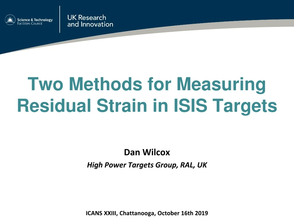
Two Methods for Measuring Residual Strain in ISIS Targets Dan Wilcox High Power Targets Group, RAL, UK ICANS XXIII, Chattanooga, October 16th 2019
Outline • Background • Asymmetric-clad strip method • Neutron diffraction method • Results and analysis • Implications for target design
Acknowledgements • Sample manufacture – Leslie Jones, Jeremy Moor, Max Rowland, Peter Webb • Asymmetric-clad concept – Peter Loveridge • Instrument scientists – Saurabh Kabra, Tung Lik Lee • ISIS management – Ste Gallimore, David Jenkins
Background • ISIS operates two spallation targets; TS1 and TS2 • Both have tungsten cores clad in tantalum for corrosion resistance • Any significant cladding breach means we have to replace the target • Causes activation of the cooling plant, which needs hands-on maintenance • Cladding is attached by Hot Isostatic Press (HIP) • Produces a strong bond with good thermal contact • High residual stress predicted from HIP – maybe more than beam heating • Exact amount of residual stress is a major unknown in current simulations* TS2 TS1 *D. Wilcox, P. Loveridge, T. Davenne, L. Jones and D. Jenkins, "Stress levels and failure modes of tantalum-clad tungsten targets at ISIS," Journal of Nuclear Materials, vol. 506, pp. 76-82, 2018.
ISIS Target Manufacture • Tantalum can welded shut with tungsten core inside • Hot Isostatic Press (HIP) process applies high temperature and pressure, bonding cladding and core • Final machining to achieve dimensional accuracy Components of TS2 target HIP assembly
ISIS Target Manufacture • HIP cycle in detail: • Cladding deforms plastically under high pressure (140MPa) • Peak temperature is 1200°C, held for 2 hours; this relieves stress, but does not cause grain growth • Tantalum and tungsten are bonded together • As the clad target cools below the annealing temperature, residual stress builds up due to different coefficients of thermal expansion: • Tungsten 4.5E-06/K • Tantalum 6.3E-06/K A typical ISIS HIP cycle
Simplifying Assumptions Simplifying assumptions for simulating residual stress: • All stress from welding and HIP pressure is relieved during HIPing • Stress due to final machining and plate welding is small compared to stress from HIPing, and can be ignored • Stress from HIP cooldown is relieved at first, but below a certain ‘lock-in’ temperature stress starts to builds up • Industry uses a stress relieving temperature of around 850°C • Lock-in temperature estimated to be 500°C, but this needs validation
Asymmetric-Clad Strip Method • Provides a simple, mechanical method of measuring residual stress after HIPing • HIP a long strip of tungsten with asymmetric tantalum cladding • The strip should deflect in proportion to the residual stress • Calculations predict a spherical surface, concave on the thick tantalum side • Dimensions optimised to produce a measurable deflection without breaking the sample Nominal dimensions of asymmetric-clad strip
Manufacture • Manufactured by Jeremy Moor and his team using the same materials and methods as ISIS targets Photos: Jeremy Moor
Measurement • Sample was measured before and after HIP using a Faro Edge arm (laser scanner coordinate measuring machine) • Concave on thick tantalum side and almost spherical, as expected • Spherical surfaces fit the upper and lower faces with r2 = 0.990 Upper surface Cloud of points from Faro arm (above) and spherical fits to upper and lower surfaces (right) Lower surface
Comparison with Theory • Compare fit and simulated radii of curvature • Estimates lock-in temperature at 385-450°C • To produce the measured deflection the tantalum must have yielded
Neutron Diffraction Method • ENGIN-X is an instrument on ISIS TS1 which uses neutron diffraction to make non-destructive strain measurements “The beamline is optimized for the measurement of strain, and thus stress, deep within a crystalline material, using the atomic lattice planes as an atomic 'strain gauge'.” https://www.isis.stfc.ac.uk/Pages/Engin-X.aspx • Good penetration depth even in Ta/W • 1x1x18mm measurement volume • Cannot measure plastic strain • Strains are calculated relative to an unstressed ‘d0’ measurement The ENGIN-X instrument: measuring residual stress within friction stir welds on an Airbus prototype wing rib
Prior Experiment by Yanling Ma et al. • Neutron diffraction experiment on ENGIN-X by Yanling Ma et al. on a TS1 plate* • Demonstrated that ENGIN-X can measure depths of up to 13mm in tantalum/tungsten in a reasonable length of time *Yanling Ma et al., “An Experiment Using Neutron Diffraction to Investigate Residual Strain Distribution in a Hot Isostatic Pressed (HIPPED) Target Plate,” in Joint 3rd UK-China Steel Research Forum & 15th CMA-UK Conference on Materials Science and Engineering, 2014.
Prior Experiment by Yanling Ma et al. • Measured elastic strains are broadly consistent with the cladding being at the yield stress as predicted – however the sample was too thick to measure all three directions so this could not be confirmed ANSYS Simulation of Engin-X Sample Engin-X Strain Result (Y direction) 662 Microstrain ≈ 600 Microstrain -749 Microstrain ≈ -300 Microstrain
ENGIN-X Measurements • Two experiments: October 2018 (3 days) and March 2019 (2 days) • Aims – measure a detailed through-thickness strain profile – check uniformity of strain profile with position – measure all 3 strain components at every point 3, 9, 3Points 9 Points 10mm 50mm 50mm 10mm 20mm Clamp this end 3 Points X Y Z
ENGIN-X Measurements • Sample rotated part way through to measure all 3 strain components • Normal direction measured twice Photos courtesy of Tung Lik Lee
ENGIN-X Results – Part 1 • Similar profiles in x and y, as expected • Good repeatability between repeat measurements • Quite good agreement with simulation apart from through-thickness (z) strain in tantalum
Changes for Second ENGIN-X Run • Previous ‘d0’ samples may not have been truly unstressed • Tantalum d0 sample was rolled and annealed • Tungsten d0 sample was forged, but probably not annealed • Repeated measurement with new d0 samples • Tungsten sample cut into combs to relieve stress from forging • Previous W sample had higher normal strain – possibly due to forging • PreviousTa sample the same to within the ≈100 microstrain uncertainty • Also re-measured old locations and added more measurement points
HIP Effects on Nominally Unstressed Samples • Second run also looked at the stress change after HIPing in pure tantalum and pure tungsten • HIP may change the atomic spacing and therefore d0 measurement • An exact copy of each d0 sample was put through a standard ISIS HIP cycle • HIPing induces a strain which is compressive in W, tensile in Ta • Changes are anisotropic, which was unexpected and makes it difficult to apply d0 corrections to other geometry e.g. the strip
ENGIN-X Results – Part 2 • Good repeatability between different locations and times • No choice of d0 measurement improves the fit for all materials and directions
Conclusions from Experiments • Presence of large tensile residual stress in cladding confirmed by physical test and neutron measurement • Simulations with lock-in temperature ≈ 400°C predict the shape of the deformed strip, but do not explain all the details seen by ENGIN-X • HIPing produces unexpected changes in neutron diffraction strain measurements of pure tantalum and tungsten samples • Differences in ENGIN-X data vs simulation may be due to: • Large uncertainties relative to measurement (high Young’s mod of Ta/W) • Creep of tantalum during cooldownafter HIPing • Deformed grains or other microstructural effects => anisotropic properties • No stress relieving was observed over time. Residual stress may relieve in-beam, but this would be difficult to measure.
Implications for Target Design • Large residual stress confirmed, so this should be taken into account in future target analysis work • High tensile stress will reduce fatigue life of the cladding, although current ISIS targets have a large safety factor even with this included • Limited data on combined radiation damage and fatigue effects • If tantalum ductility is lost this may present a problem • Not currently an issue, but could be for potential ISIS-2 targets • Continuing to develop our understanding of failure modes will enable more optimised targets and higher beam powers in future