Download
1 / 16
160 likes | 296 Vues
Prototype SKA technologies at Molonglo – 1. Overview & Science Goals. A.J. Green, J.D. Bunton, D. Campbell-Wilson, L.E. Cram, R.G. Davison, R.W. Hunstead, D.A. Mitchell, A.J. Parfitt, E.M. Sadler, G.B. Warr.

E N D
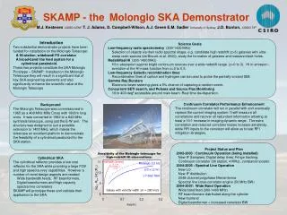
Prototype SKA technologies at Molonglo – 1. Overview & Science Goals A.J. Green, J.D. Bunton, D. Campbell-Wilson, L.E. Cram, R.G. Davison, R.W. Hunstead, D.A. Mitchell, A.J. Parfitt, E.M. Sadler, G.B. Warr Joint project between the University of Sydney, Australia Telescope National Facility and CSIRO Telecommunications and Industrial Physics Goal: To equip the Molonglo telescope with new feeds, low-noise amplifiers, digital filterbank and FX correlator with the joint aims of (i) developing and testing SKA-relevant technologies and(ii) providing a new national research facility for low-frequency radio astronomy Funding proposal: Part of Australian astronomy community’s bid to 2001 Major National Research Facilities scheme. SKA Technologies at Molonglo
Current wide-field imaging with MOST (843 MHz, 12hr synthesis, 2.7o diameter field) Current Survey (1997-2003): The Sydney University Molonglo Sky Survey (SUMSS), imaging the whole southern sky (d<-30o) at 843 MHz to mJy sensitivity with 45” resolution (i.e. similar to NVSS). Next: Use existing telescope as SKA testbed and science facility: - Large collecting area (18,000 m2) - Wide field of view - Continuous uv coverage Photo: D. Bock SKA Technologies at Molonglo
Continuous uv coverage gives excellent image quality: 750 m 1.6 km (Bock et al. 1999) • Continuous uv coverage from 90 m to 1.6 km in 12hr synthesis • SKA will also have fully-sampled uv data SKA Technologies at Molonglo
Key features of the Molonglo SKA prototype Collecting area = 1% of SKA (i.e. equivalent to 1 SKA station) • Multibeaming • Wide instantaneous field of view • Digital beamforming • Wide-band FX correlator (2048 channels) • Frequency and pointing agility • Wide-band line feeds and LNAs • Cylindrical antenna prototype • Adaptive null steering and adaptive noise cancellation SKA Technologies at Molonglo
Cylindrical Parabolic Collectors (Two collinear 778 m x 12 m) 300-1420 MHz Feed and LNA (7,400 feeds, 14,800 LNAs) Single feed beam Delay line beam Independent fanbeam Imaging beam Delay line beamforming Analog to Digital Converter (1,600 8 bit 250 MHz BW ADCs) Digital delay beamforming (80 x10 m x 10 m patches) Digital filterbank (160) (Two polarisations @ 250 MHz/patch) Independent fanbeam FX Correlator (3,160 baselines, 2,048 channels) Digital Beamformer (64 fanbeams within imaging beam) [Requires extra funding] Signal processing & storage (imaging, spectrometer, searching...) Signal Path and Antenna Pattern SKA Technologies at Molonglo
Target specifications SKA Technologies at Molonglo
Links between technology and science goals: 1. High-redshift radio galaxies FX correlator: wide-band radio spectrometry Radio spectral index measurements over the range 300 –1400 MHz are an efficient way of selecting high-redshift (z>3) radio galaxies (e.g. de Breuck et al. 2000). Radio galaxy TN0924-2201 at z=5.19(van Breugel et al. 1999) SKA Technologies at Molonglo
Links between technology and science goals: 2. High-redshift HI in galaxies HIPASS (500s) (12 h) Molonglo (10x12 h) log10 Mlim (HI) (M⊙) Typical bright spiral HI in the nearby Circinus galaxy (Jones et al. 1999) The Molonglo telescope will reach HI mass limits typical of bright spiral galaxies at z=0.2 (lookback time ~3 Gyr), allowing a direct measurement of evolution in the HI mass function. SKA Technologies at Molonglo
Links between technology and science goals: 3. Other science projects • Redshifted HI absorption (z=0 to 3) • OH megamasers • Galactic recombination lines (H,C) FX correlator (2048 channels, each 0.2–25 km/s) Pointing agility • Rapid response to GRBs Independent fan beam • Monitoring programs (pulsars etc.) Optional 64 fanbeams within main beam • SETI, pulsar searches (high sensitivity, wide field of view) SKA Technologies at Molonglo
Timescales 2002: Design studies 2003: 2 x 10m test patches instrumented with filterbanks and single-baseline correlator 2004: Whole telescope instrumented, commissioning and test observing 2005: Science program begins SKA Technologies at Molonglo
For more information: Three papers at this meeting: Prototype SKA technologies at Molonglo: 1. Overview and science goals (Green et al.) 2. Antenna and front end (Warr et al.) 3. Beamformer and correlator (Bunton) Web pages: www.physics.usyd.edu.au/astrop www.atnf.csiro/ska SKA Technologies at Molonglo
RFI at Molonglo 200-1500 MHz (Measured 25 June 2001) UHF TV VHF TV GSM SKA Technologies at Molonglo
beam size: 112” x 112” csc|d| Rengelink et al 1997 WENSS 325 MHz beam size: 43” x 43” csc|d| beam size: 26” x 26” csc|d| Bock et al 1999 SUMSS 843 MHz Wall 1994 1420 MHz Molonglo continuum confusion (10 beams/source) at δ= -60° SKA Technologies at Molonglo
x focus Molonglo parabola design accurate to > 1400 MHz Piecewise linear fit to parabola shape Flat mesh tied on supports at points shown • Mesh supported at 0.6 m (2 ft) intervals in x direction. • Each section gives the same error for a linear fit to a parabola. • Gives only 0.1 dB loss at 1420 MHz. SKA Technologies at Molonglo
Patch positions on reflectors -800 0 800 Distance (m) Synthesised Beam Shape Beam Shape The synthesised beam shape for a possible configuration of antenna patches on the telescope is shown. This configuration has a contiguous patch covering a third of the telescope area for forming 1.3’ beams for pulsar or SETI searches. The remaining part of the telescope is more sparsely covered (with positions calculated from a simple grading function) to give good imaging resolution. SKA Technologies at Molonglo
Beamformer and Correlator Beamforming and Digital Filterbanks for one of 44 bays Analog delay line beamforming Accuracy /4 Each polarisation RF 0.3 to 1.4GHz LO 2.2 to 0.9GHz IF at 2.5 GHz Quadrature baseband detection Dual 250 MSamples/s 8-bit A/Ds generating a complex 250 MHz signal Digital Beamforming Fine delays accuracy /16 Delay corrects for average analog delay error Arbitrary and time varying grading Modifiable beam shape with meridian distance Resources for adaptive null steering 250 MHz complex digital filterbanks 120 kHz frequency channels Single FPGA implementation Adaptive noise cancellation on a per channel basis SKA Technologies at Molonglo