Download
1 / 62
620 likes | 813 Vues
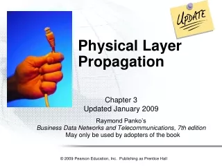
Chapter 4 Section A. Physical Principles of Propagation. Introduction to Propagation. Propagation is the heart of every radio link. During propagation, many processes act on the radio signal. attenuation

E N D
Chapter 4 Section A Physical Principles of Propagation RF100 (c) 1998 Scott Baxter
Introduction to Propagation • Propagation is the heart of every radio link. During propagation, many processes act on the radio signal. • attenuation • the signal amplitude is reduced by various natural mechanisms. If there is too much attenuation, the signal will fall below the reliable detection threshold at the receiver. Attenuation is the most important single factor in propagation. • multipath and group delay distortions • the signal diffracts and reflects off irregularly shaped objects, producing a host of components which arrive in random timings and random RF phases at the receiver. This blurs pulses and also produces intermittent signal cancellation and reinforcement. These effects are overcome through a variety of special techniques • time variability - signal strength and quality varies with time, often dramatically • space variability - signal strength and quality varies with location and distance • frequency variability - signal strength and quality differs on different frequencies • To master propagation and effectively design wireless systems, you must know: • Physics: understand the basic propagation processes • Measurement: obtain data on propagation behavior in area of interest • Statistics: analyze known data, extrapolate to predict the unknown • Modelmaking: formalize all the above into useful models RF100 (c) 1998 Scott Baxter
l/2 Frequency and Wavelength: Implications • Radio signals in the atmosphere propagate at almost speed of light l= wavelength C = distance propagated in 1 second F = frequency, Hertz • The wavelength of a radio signal determines many of its propagation characteristics • Antenna elements size are typically in the order of 1/4 to 1/2 wavelength • Objects bigger than a wavelength can reflect or obstruct RF energy • RF energy can penetrate into a building or vehicle if they have apertures a wavelength in size, or larger l = C / F for AMPS: F= 870 MHz l= 0.345 m = 13.6 inches for PCS-1900: F = 1960 MHz l= 0.153 m = 6.0 inches RF100 (c) 1998 Scott Baxter
Propagation Effects of Earth’s Atmosphere • Earth’s unique atmosphere supports life (ours included) and also introduces many propagation effects -- some useful, some troublesome • Skywave Propagation: reflection from Ionized Layers • LF and HF frequencies (below roughly 50 MHz.) are routinely reflected off layers of the upper atmosphere which become ionized by the sun • this phenomena produces intermittent world-wide propagation and occasional total outages • this phenomena is strongly correlated with frequency, day/night cycles, variations in earth’s magnetic field, 11-year sunspot cycle • these effects are negligible for wireless systems at their much-higher frequencies RF100 (c) 1998 Scott Baxter
“Rain Fades” on MIcrowave Links Refraction by air layers Ducting by air layers >100 mi. More Atmospheric Propagation Effects • Attenuation at Microwave Frequencies • rain droplets can substantially attenuate RF signals whose wavelengths are comparable to, or smaller than, droplet size • rain attenuations of 20 dB. or more per km. are possible • troublesome mainly above 10 GHz., and in tropical areas • must be considered in reliability calculations during path design • not major factor in wireless systems propagation • Diffraction, Wave Bending, Ducting • signals 50-2000 MHz. can be bent or reflected at boundaries of different air density or humidity • phenomena: very sporadic unexpected long-distance propagation beyond the horizon. May last minutes or hours • can occur in wireless systems RF100 (c) 1998 Scott Baxter
Free Space d D A B Reflection with partial cancellation Knife-edge Diffraction Dominant Mechanisms of Mobile Propagation Most propagation in the mobile environment is dominated by these three mechanisms: • Free space • No reflections, no obstructions • first Fresnel Zone clear • Signal spreading is only mechanism • Signal decays 20 dB/decade • Reflection • Reflected wave 180°out of phase • Reflected wave not attenuated much • Signal decays 30-40 dB/decade • Knife-edge diffraction • Direct path is blocked by obstruction • Additional loss is introduced • Formulae available for simple cases • We’ll explore each of these further... RF100 (c) 1998 Scott Baxter
r Free Space “Spreading” Loss energy intercepted by receiving antenna is proportional to 1/r2 d 1st Fresnel Zone A D First Fresnel Zone = {Points P where AP + PB - AB < l/2 } Fresnel Zone radius d = 1/2 (lD)^(1/2) B Free-Space Propagation • The simplest propagation mode • Antenna radiates energy which spreads in space • Path Loss, db (between two isotropic antennas) = 36.58 +20*Log10(FMHZ)+20Log10(DistMILES ) • Path Loss, db (between two dipole antennas) = 32.26 +20*Log10(FMHZ)+20Log10(DistMILES ) • Notice the rate of signal decay: • 6 db per octave of distance change, which is 20 db per decade of distance change • Free-Space propagation is applicable if: • there is only one signal path (no reflections) • the path is unobstructed (i.e., first Fresnel zone is not penetrated by obstacles) RF100 (c) 1998 Scott Baxter
Heights Exaggerated for Clarity HTFT HTFT DMILES SCALE PERSPECTIVE Comparison of Free-Space and Reflection Propagation Modes Assumptions: Flat earth, TX ERP = 50 dBm, @ 1950 MHz. Base Ht = 200 ft, Mobile Ht = 5 ft. DistanceMILES 1 2 4 6 8 10 15 20 Received Signal in Free Space, DBM -52.4 -58.4 -64.4 -67.9 -70.4 -72.4 -75.9 -78.4 Received Signal in Reflection Mode -69.0 -79.2 -89.5 -95.4 -99.7 -103.0 -109.0 -113.2 Reflection With Partial Cancellation • Mobile environment characteristics: • Small angles of incidence and reflection • Reflection is unattenuated (reflection coefficient =1) • Reflection causes phase shift of 180 degrees • Analysis • Physics of the reflection cancellation predicts signal decay of 40 dB per decade of distance • Path Loss [dB ]= 172 + 34 x Log(DMiles ) • - 20 x Log (Base Ant. HtFeet) • - 10 x Log(Mobile Ant. HtFeet) RF100 (c) 1998 Scott Baxter
Signal Level vs. Distance 0 -10 -20 -30 -40 1 2 3.16 5 6 7 8 10 Distance, Miles One Decade of distance (10x) One Octave of distance (2x) Signal Decay Rates in Various Environments We’ve seen how the signal decays with distance in two basic modes of propagation: • Free-Space • 20 dB per decade of distance • 6 db per octave of distance • Reflection Cancellation • 40 dB per decade of distance • 12 db per octave of distance • Real-life wireless propagation decay rates are typically somewhere between 30 and 40 dB per decade of distance RF100 (c) 1998 Scott Baxter
H R1 R2 ( + ) 2 l 1 1 R1R2 n = -H 0 -5 atten dB -10 -15 -20 -25 -5 -4 -3 -2 -1 0 1 2 3 n Knife-Edge Diffraction • Sometimes a single well-defined obstruction blocks the path, introducing additional loss. This calculation is fairly easy and can be used as a manual tool to estimate the effects of individual obstructions. • First calculate the diffraction parameter nfrom the geometry of the path • Next consult the table to obtain the obstruction loss in db • Add this loss to the otherwise-determined path loss to obtain the total path loss. • Other losses such as free space and reflection cancellation still apply, but computed independently for the path as if the obstruction did not exist RF100 (c) 1998 Scott Baxter
Multi-path Propagation Rayleigh Fading l/2 A 10-15 dB d Local Variability: Multipath Effects • The free-space, reflection, and diffraction mechanisms described earlier explain signal level variations on a large scale, but other mechanisms introduce small-scale local fading • Slow Fading occurs as the user moves over hundreds of wavelengths due to shadowing by local obstructions • Rapid Fading occurs as signals received from many paths drift into and out of phase • the fades are roughly l/2 apart in space: 7 inches apart at 800 MHz., 3 inches apart at 1900 MHz • fades also appear in the frequency domain and time domain • fades are typically 10-15 db deep, occasionally deeper • Rayleigh distribution is a good model for these fades • these fades are often called “Rayleigh fades” RF100 (c) 1998 Scott Baxter
D Signal received by Antenna 1 Signal received by Antenna 2 Combined Signal Combating Rayleigh Fading: Space Diversity • Fortunately, Rayleigh fades are very short and last a small percentage of the time • Two antennas separated by several wavelengths will not generally experience fades at the same time • “Space Diversity” can be obtained by using two receiving antennas and switching instant-by-instant to whichever is best • Required separation D for good decorrelation is 10-20l • 12-24 ft. @ 800 MHz. • 5-10 ft. @ 1900 MHz. RF100 (c) 1998 Scott Baxter
D Signal received by Antenna 1 Signal received by Antenna 2 Combined Signal Space Diversity Application Limitations • Space Diversity can be applied only on the receiving end of a link. • Transmitting on two antennas would: • fail to produce diversity, since the two signals combine to produce only one value of signal level at a given point -- no diversity results. • produce objectionable nulls in the radiation at some angles • Therefore, space diversity is applied only on the “uplink”, i.e.., reverse path • there isn’t room for two sufficiently separated antennas on a mobile or handheld RF100 (c) 1998 Scott Baxter
V+H or \+/ A B A B Antenna A Antenna B Combined Using Polarization DiversityWhere Space Diversity Isn’t Convenient • Sometimes zoning considerations or aesthetics preclude using separate diversity receive antennas • Dual-polarized antenna pairs within a single radome are becoming popular • Environmental clutter scatters RF energy into all possible polarizations • Differently polarized antennas receive signals which fade independently • In urban environments, this is almost as good as separate space diversity • Antenna pair within one radome can be V-H polarized, or diagonally polarized • Each individual array has its own independent feedline • Feedlines connected to BTS diversity inputs in the conventional way; TX duplexing OK RF100 (c) 1998 Scott Baxter
-148.21 db @ 870.03 MHz -148.21 db @ 835.03 MHz -151.86 db @ 870.03 MHz The Reciprocity PrincipleDoes it apply to Wireless? Between two antennas, on the same exact frequency, path loss is the same in both directions • But things aren’t exactly the same in cellular -- • transmit and receive 45 MHz. apart • antenna: gain/frequency slope? • different Rayleigh fades up/downlink • often, different TX & RX antennas • RX diversity • Notice also the noise/interference environment may be substantially different at the two ends • So, reciprocity holds only in a general sense for cellular RF100 (c) 1998 Scott Baxter
Chapter 4 Section B Propagation Models RF100 (c) 1998 Scott Baxter
Examples of various model types • Simple Analytical • Free space (Friis formula) • Reflection cancellation • Knife-edge diffraction • Area • Okumura-Hata • Euro/Cost-231 • Walfisch-Betroni/Ikegami • Point-to-Point • Ray Tracing • Lee’s Method, others • Tech-Note 101 • Longley-Rice, Biby-C • Local Variability • Rayleigh Distribution • Normal Distribution • Joint Probability Techniques Types Of Propagation Models And Their Uses • SimpleAnalyticalmodels • Used for understanding and predicting individual paths and specific obstruction cases • General Areamodels • Primary drivers: statistical • Used for early system dimensioning (cell counts, etc.) • Point-to-Pointmodels • Primary drivers: analytical • Used for detailed coverage analysis and cell planning • Local Variabilitymodels • Primary drivers: statistical • Characterizes microscopic level fluctuations in a given locale, confidence-of-service probability RF100 (c) 1998 Scott Baxter
-50 +90 +80 -60 +70 -70 Field Strength, dBµV/m -80 +60 RSSI, dBm -90 +50 -100 +40 -110 +30 -120 +20 0 3 6 9 12 15 18 21 24 27 30 33 Distance from Cell Site, km • Green Trace shows actual measured signal strengths on a drive test radial, as determined by real-world physics. • Red Trace shows the Okumura-Hata prediction for the same radial. The smooth curve is a good “fit” for real data. However, the signal strength at a specific location on the radial may be much higher or much lower than the simple prediction. General Principles Of Area Models • Area models mimic an averagepath in a defined area • They’re based on measured data alone, with no consideration of individual path features or physical mechanisms • Typical inputs used by model: • Frequency • Distance from transmitter to receiver • Actual or effective base station & mobile heights • Average terrain elevation • Morphology correction loss(Urban, Suburban, Rural, etc.) • Results may be quite different than observed on individual paths in the area RF100 (c) 1998 Scott Baxter
70 Urban Area 35 100 30 Open area 80 25 50 Correction factor, Garea (dB) Quasi open area 70 d, km 20 Median Attenuation A(f,d), dB 40 15 Suburban area 30 10 26 9 dB 5 2 5 1 850 MHz 850 10 100 200 300 500 700 1000 2000 3000 100 500 3000 Frequency f, (MHz) Frequency f, MHz The Okumura Model: General Concept The Okumura model is based on detailed analysis of exhaustive drive-test measurements made in Tokyo and its suburbs during the late 1960’s and early 1970’s. The collected date included measurements on numerous VHF, UHF, and microwave signal sources, both horizontally and vertically polarized, at a wide range of heights. The measurements were statistically processed and analyzed with respect to almost every imaginable variable. This analysis was distilled into the curves above, showing a median attenuation relative to free space loss Amu (f,d) and correlation factor Garea (f,area), for BS antenna height ht = 200 m and MS antenna height hr= 3 m. Okumura has served as the basis for high-level design of many existing wireless systems, and has spawned a number of newer models adapted from its basic concepts and numerical parameters. RF100 (c) 1998 Scott Baxter
Path Loss [dB] = LFS+ Amu(f,d)- G(Hb)- G(Hm) - Garea Morphology Gain 0 dense urban 5 urban 10 suburban 17 rural Free-Space Path Loss Base Station Height Gain = 20 x Log (Hb/200) Amu(f,d)Additional Median Loss from Okumura’s Curves Mobile Station Height Gain = 10 x Log (Hm/3) 35 70 Urban Area 30 100 Open area 25 80 Quasi open area 50 d, km 70 20 Correction factor, Garea (dB) Median Attenuation A(f,d), dB 15 40 Suburban area 30 10 26 5 5 2 850 MHz 1 Frequency f, MHz 850 200 300 500 700 1000 2000 3000 10 100 100 500 3000 Frequency f, (MHz) Structure of the Okumura Model • The Okumura Model uses a combination of terms from basic physical mechanisms and arbitrary factors to fit 1960-1970 Tokyo drive test data • Later researchers (HATA, COST231, others) have expressed Okumura’s curves as formulas and automated the computation RF100 (c) 1998 Scott Baxter
The Hata Model: General Concept • The Hata model is an empirical formula for propagation loss derived from Okumura’s model, to facilitate automatic calculation. • The propagation loss in an urban area is presented in a simple general format A + B x log R, where A and B are functions of frequency and antenna height, R is distance between BS and MS antennas • The model is applicable to frequencies 100 MHz-1500 MHz, distances 1-20 km, BS antenna heights 30-200 m, MS antenna heights 1-10 m • The model is simplified due to following limitations: • Isotropic antennas • Quasi-smooth (not irregular) terrain • Urban area propagation loss is presented as the standard formula • Correction equations are used for other areas • Although Hata model does not imply path-specific corrections, it has significant practical value and provide predictions which are very closely comparable with Okumura’s model RF100 (c) 1998 Scott Baxter
Hata Model General Concept and Formulas (1) LHATA (urban) [dB] =69.55 + 26.16 x log ( f ) + [ 44.9 - 6.55 x log ( hb ) ] x log ( d ) -13.82 x log ( hb ) - A ( hm ) (2) LHATA (suburban) [dB] = LHATA (urban) - 2 x [ log ( f/28 ) ]2 - 5.4 (3) LHATA (rural) [dB] =LHATA (urban) - 4.78 x [ log ( f ) ]2 - 18.33 x log ( f ) -40.98 (4) A ( hm ) [dB] = [ 11 x log ( f ) - 0.7 ] x hm - [ 1.56 x log ( f ) - 0.8 ] (5) A ( hm ) [dB] = 8.29 x [ log ( 1.54 x hm ) ]2 - 1.1 (for f<= 300 MHz.) (6) A ( hm ) [dB] = 3.2 x [ log ( 1175 x hm ) ]2 - 4.97 (for f > 300 MHz.) Formulas for median path loss are:(1) - Standard formula for urban areas(2) - For suburban areas(3) - For rural areas Formulas for MS antenna ht. gain correction factor A(hm)(4) - For a small to medium sizes cities(5) and (6) - For large cities f - carrier frequency, MHz hb and hm - BS and MS antenna heights, m d - distance between BS and MS antennas, km Environmental Factor C 0 dense urban -5 urban -10 suburban -17 rural RF100 (c) 1998 Scott Baxter
The EURO COST-231 Model LCOST (urban) [dB] = 46.3 + 33.9 x log ( f ) + [ 44.9 - 6.55 x log ( hb ) ] x log ( d ) + Cm -13.82 x log ( hb ) - A ( hm ) The COST-231 model was developed by European COoperative for Scientific and Technical Research committee. It extends the HATA model to the 1.8-2 GHz. band in anticipation of PCS use. • COST-231 is applicable for frequencies 1500-2000 MHz, distances 1-20 km, BS antenna heights 30-200 m, MS antenna heights 1-10 m • Parameters and variables: • f is carrier frequency , in MHz • hb and hm are BS and MS antenna heights (m) • d is BS and MS separation, in km • A(hm) is MS antenna height correction factor (same as in Hata model) • Cm is city size correction factor: Cm=0 dB for suburbs and Cm=3 dB for metropolitan centers Environmental Factor C 1900 -2 dense urban -5 urban -10 suburban -26 rural RF100 (c) 1998 Scott Baxter
Suburban Suburban Urban Urban Dense Urban Dense Urban Examples of Morphological Zones • Suburban: Mix of residential and business communities. Structures include 1-2 story houses 50 feet apart and 2-5 story shops and offices. • Urban: Urban residential and office areas (Typical structures are 5-10 story buildings, hotels, hospitals, etc.) • DenseUrban: Dense business districts with skyscrapers (10-20 stories and above) and high-rise apartments Although zone definitions are arbitrary, the examples and definitions illustrated above are typical of practice in North American PCS designs. RF100 (c) 1998 Scott Baxter
Rural - Highway Rural - Highway Rural Rural Suburban Suburban Example Morphological Zones • Rural - Highway: Highways near open farm land, large open spaces, and sparsely populated residential areas. Typical structures are 1-2 story houses, barns, etc. • Rural - In-town: Open farm land, large open spaces, and sparsely populated residential areas. Typical structures are 1-2 story houses, barns, etc. Notice how different zones may abruptly adjoin one another. In the case immediately above, farm land (rural) adjoins built-up subdivisions (suburban) -- same terrain, but different land use, penetration requirements, and anticipated traffic densities. RF100 (c) 1998 Scott Baxter
The MSI Planet General Model Pr = Pt + K1 + k2 log(d) + k3 log(Hb) + K4 DL + K5 log(Hb) log(d) + K6 log (Hm) + Kc + Ko This is the general model format used in MSI’s popular PlaNET propagation prediction software for wireless systems. It includes terms similar to Okumura-Hata and COST-231 models, along with additional terms to include effects of specific obstructions and clutter on specific paths in the mobile environment. Pr - received power (dBm) Pt - transmit ERP (dBm) Hb - base station effective antenna height Hm - mobile station effective antenna height DL - diffraction loss (dB) K1 - intercept K2 - slope K3 - correction factor for base station antenna height gain K4 - correction factor for diffraction loss (accounts for clutter heights) K5 - Okumura-Hata correction factor for antenna height and distance K6 - correction factor for mobile station antenna height gain Kc - correction factor due to clutter at mobile station location Ko - correction factor for street orientation RF100 (c) 1998 Scott Baxter
Tower Height, m EIRP (watts) C, dB Range, km COST-231/Hata f =1900 MHz. Dense Urban 30 200 -2 2.52 Urban 30 200 -5 3.50 Suburban 30 200 -10 4.8 Rural 50 200 -26 10.3 Tower Height, m EIRP (watts) C, dB Range, km Okumura/Hata f = 870 MHz. Dense Urban 30 200 0 4.0 Urban 30 200 -5 4.9 Suburban 30 200 -10 6.7 Rural 50 200 -17 26.8 Typical Model Results Including Environmental Correction RF100 (c) 1998 Scott Baxter
Propagation at 1900 MHz. vs. 800 MHz. • Propagation at 1900 MHz. is similar to 800 MHz., but all effects are more pronounced. • Reflections are more effective • Shadows from obstructions are deeper • Foliage absorption is more attenuative • Penetration into buildings through openings is more effective, but absorbing materials within buildings and their walls attenuate the signal more severely than at 800 MHz. • The net result of all these effects is to increase the “contrast” of hot and cold signal areas throughout a 1900 MHz. system, compared to what would have been obtained at 800 MHz. • Overall, coverage radius of a 1900 MHz. BTS is approximately two-thirds the distance which would be obtained with the same ERP, same antenna height, at 800 MHz. RF100 (c) 1998 Scott Baxter
Area View -20 dBm Signal Level Legend -30 dBm -40 dBm -50 dBm -60 dBm -70 dBm -80 dBm -90 dBm -100 dBm -110 dBm -120 dBm Walfisch-Betroni/Walfisch-Ikegami Models • Ordinary Okumura-type models do work in this environment, but the Walfisch models attempt to improve accuracy by exploiting the actual propagation mechanisms involved Path Loss = LFS + LRT + LMS LFS= free space path loss(Friis formula) LRT = rooftop diffraction loss LMS = multiscreen reflection loss • Propagation in built-up portions of cities is dominated by ray diffraction over the tops of buildings and by ray “channeling” through multiple reflections down the street canyons RF100 (c) 1998 Scott Baxter
Signal Strength Predicted Vs. Observed Model is tweaked to produce “Best-Fit” curve Observed Signal Strength RSSI, dBm 50% of observed data is above curve 50% of observed data is below curve Distance Normal Distribution Occurrences RSSI Median Signal Strength s, dB Statistical TechniquesDistribution Statistics Concept • An area model predicts signal strength Vs. distance over an area • This is the “median” or most probable signal strength at every distance from the cell • The actual signal strength at any real location is determined by local physical effects, and will be higher or lower • It is feasible to measure the observed median signal strength M and standard deviation s • Mand s can be applied to find probability of receiving an arbitrary signal level at a given distance RF100 (c) 1998 Scott Baxter
SIGNAL STRENGTH vs DISTANCE RSSI, dBm 25% of locations exceed blue curve 50% exceed red 75% exceed black Min signal req’d for operation Distance Cell radius for 75% reliability at edge Cell radius for 75% reliability at edge Cell radius for 90% reliability at edge Normal Distribution Occurrences RSSI Median Signal Strength s, dB Statistical TechniquesPractical Application Of Distribution Statistics • General Approach: • Use favorite model to predict Signal Strength • Analyze measured data, obtain: • median signal strength M • (build histogram of observed vs. measured data) • standard deviation of error, s • (determine from histogram) • add an extra allowance into model • drop curve so a desired % of observations are above model predictions RF100 (c) 1998 Scott Baxter
Statistical View of Cell Coverage 75% 90% Area Availability: 90% overall within area 75%at edge of area Cell Edge Area Availability And Probability Of Service • Overall probability of service is best close to the BTS, and decreases with increasing distance away from BTS • For overall 90% location probability within cell coverage area, probability will be 75% at cell edge • Result derived theoretically, confirmed in modeling with propagation tools, and observed from measurements • True if path loss variations are log-normally distributed around predicted median values, as in mobile environment • 90%/75% is a commonly-used wireless numerical coverage objective • Recent publications by Nortel’s Dr. Pete Bernardin describe the relationship between area and edge reliability, and the field measurement techniques necessary to demonstrate an arbitrary degree of coverage reliability RF100 (c) 1998 Scott Baxter
Cumulative Normal Distribution 100% 90% 80% 75% 70% 60% 50% 40% 30% 20% 0.675s 10% 0% -3 -2.5 -2 -1.5 -1 -0.5 0 0.5 1 1.5 2 2.5 3 Standard Deviations from Median (Average) Signal Strength Application Of Distribution Statistics: Example • Let’s design a cell to deliver at least -95 dBm to at least 75% of the locations at the cell edge (This will provide coverage to 90% of total locations within the cell) • Assume that measurements you have made show a 10 dB standarddeviation s • On the chart: • To serve 75% of locations at the cell edge , we must deliver a median signal strength which is .675 times s stronger than -95 dBm • Calculate:- 95 dBm + ( .675 x 10 dB ) = - 88 dBm • So, design for a median signal strength of -88 dBm! RF100 (c) 1998 Scott Baxter
Cumulative Normal Distribution Standard Deviation Cumulative Probability 100% -3.09 0.1% 90% -2.32 1% 80% -1.65 5% 70% -1.28 10% -0.84 20% 60% -0.52 30% 50% 0 50% 40% 0.52 70% 30% 0.675 75% 20% 0.84 80% 1.28 90% 10% 1.65 95% 0% 2.35 99% -3 -2.5 -2 -1.5 -1 -0.5 0 0.5 1 1.5 2 2.5 3 3.09 99.9% Standard Deviation from Mean Signal Strength 3.72 99.99% 4.27 99.999% Statistical Techniques:Normal Distribution Graph & Table For Convenient Reference RF100 (c) 1998 Scott Baxter
Building penetration Vehicle penetration Typical Penetration Losses, dB compared to outdoor street level EnvironmentType(“morphology”) MedianLoss,dB Std. Dev. s, dB Dense Urban Bldg. 20 8 Urban Bldg. 15 8 Suburban Bldg. 10 8 Rural Bldg. 10 8 Typical Vehicle 8 4 Building PenetrationStatistical Characterization • Statistical techniques are effective against situations that are difficult to characterize analytically • Many analytical parameters, all highly variable and complex • Building coverage is modeled using existing outdoor path loss plus an additional “building penetration loss” • Median value estimated/sampled • Statistical distribution determined • Standard deviation estimated or measured • Additional margin allowed in link budget to offset assumed loss • Typical values are shown at left RF100 (c) 1998 Scott Baxter
Building sCOMPOSITE = ((sOUTDOOR)2+(sPENETRATION)2)1/2 Outdoor Loss + Penetration Loss LOSSCOMPOSITE = LOSSOUTDOOR+LOSSPENETRATION Composite Probability Of ServiceAdding Multiple Attenuating Mechanisms • For an in-building user, the actual signal level includes regular outdoor path attenuation plus building penetration loss • Both outdoor and penetration losses have their own variabilities with their own standard deviations • The user’s overall composite probability of service must include composite median and standard deviation factors RF100 (c) 1998 Scott Baxter
sCOMPOSITE = ((sOUTDOOR)2+(sPENETRATION)2)1/2 = ((8)2+(8)2)1/2 =(64+64)1/2 =(128)1/2 = 11.31 dB On cumulative normal distribution curve, 75% probability is 0.675 sabove median. Fade Margin required = (11.31) · (0.675) = 7.63 dB. Cumulative Normal Distribution 100% 90% Composite Probability of Service Calculating Required Fade Margin 80% 75% 70% EnvironmentType(“morphology”) Building Penetration Out- Door Composite Total 60% MedianLoss,dB Std. Dev. s, dB Std. Dev. s, dB Area Availability Target, % Fade Margin dB 50% 40% 30% Dense Urban Bldg. 20 8 8 90%/75% @edge 7.6 20% Urban Bldg. 15 8 8 90%/75% @edge 7.6 10% Suburban Bldg. 10 8 8 90%/75% @edge 7.6 0% .675 Rural Bldg. 10 8 8 90%/75% @edge 7.6 -3 -2.5 -2 -1.5 -1 -0.5 0 0.5 1 1.5 2 2.5 3 Standard Deviations from Median (Average) Signal Strength Typical Vehicle 8 4 8 90%/75% @edge 6.0 Composite Probability of ServiceCalculating Fade Margin For Link Budget • Example Case: Outdoor attenuation sis 8 dB., and penetration loss s is 8 dB. Desired probability of service is 75% at the cell edge • What is the composite s? How much fade margin is required? RF100 (c) 1998 Scott Baxter
Chapter 4 Section C Commercial Propagation Prediction Software RF100 (c) 1998 Scott Baxter
Point-To-Point Path-Driven Prediction Models • Use of models based on deterministic methods • Use of terrain data for construction of path profile • Path analysis (ray tracing) for obstruction, reflection analysis • Appropriate algorithms applied for best emulation of underlying physics • May include some statistical techniques • Automated point-to-point analysis for enough points to appear to provide large “area” coverage on raster or radial grid • Commonly-used Resources • Terrain databases • Morphological/Clutter Databases • Databases of existing and proposed sites • Antenna characteristics databases • Unique user-defined propagation models RF100 (c) 1998 Scott Baxter
Path-Driven Propagation Prediction Tools Data Structure Geographic “Overlay” Format: • Output Map(s) on screen or plotter • Coverage • field strengths @ probability • probabilities @ field strength • Best-Server • C/I (Adjacent Channel & Co-Channel) • Cell locations, cell grid • Terrain elevation data • USGS & Commercial databases • Satellite or aerial photography • Clutter data • Roads, rivers, railroads, etc. • State, county, MTA, BTA boundaries • Traffic density overlay • Land use overlay RF100 (c) 1998 Scott Baxter
The World as “seen” by a Propagation Prediction Tool Propagation tools use a terrain database, clutter data for land use, and vectors to represent features and traffic levels. The figure at right is a 3-D view of such databases in the area of this demonstration. Notice the granularity of the data and the very mild terrain undulations in the area, exaggerated 8 times in this view. RF100 (c) 1998 Scott Baxter
Survey Of Commercially Available Tools • RF Prediction Software Tools • Qualcomm • QEDesign CDMA Tool (Unix) • MSI • PlaNet (Unix) • LCC • CellCad (Unix) • ANet (DOS PC) • CNET • Wings (Unix) • Solutions (mainframe) • ComSearch • IQSignum (Unix) • AT&T • PACE (DOS PC) • Motorola • proprietary (Unix) • TEC Cellular: Wizard (DOS) • Elebra: CONDOR, CELTEC • Virginia Tech MPRG • SMT-Plus Indoor Site Planning Tool • A wide variety of software tools are available for propagation prediction and system design • Some tools are implemented on PC/DOS/Windows platforms, others on more powerful UNIX platform • Capabilities and user interfaces vary greatly • Several of the better-known tools for cellular RF engineering are shown in the table at right RF100 (c) 1998 Scott Baxter
Composite Coverage Plot • A composite coverage plot shows the overall coverage produced by each sector in the field of view • The color of each pixel corresponds to the signal level of the strongest server at that point • Such plots are useful for identifying coverage holes and overall coverage extent RF100 (c) 1998 Scott Baxter
Equal Power Handoff Boundaries Plot • A Best Server Plot or in CDMA terms, an Equal Power Handoff Boundaries plot paints each pixel with a unique color to identify the best-serving sector at that point • the boundaries shown are the equal-power points between cells • This type of plot is extremely useful in creating initial neighbor lists and identifying areas of no dominant server • Some tools (MSI Planet) can generate automatic neighbor lists from such a plot RF100 (c) 1998 Scott Baxter
Qualcomm’s QEDesign Qualcomm’s commercial tool QEDesign offers a number of features targeted at CDMA system design and analysis. The figures above show the output of its microcell propagation analysis tool in the Washington, DC area, and a three-dimensional view of an antenna pattern. Other features of this package include live cursor mode in which the user can drag the cursor about and see in near-real-time the line-of-sight area visible from the selected location, or a coverage footprint calculated from that location. RF100 (c) 1998 Scott Baxter
-20 dBm -30 dBm -40 dBm -50 dBm Signal Level Legend -60 dBm -70 dBm -80 dBm -90 dBm -100 dBm -110 dBm -120 dBm >20 dB C/I Legend <20 dB <17 dB <14 dB General Survey Of Tool Features Universal Basic Features of Most Tools • Automatically calculates signal strength at many points over a geographic area • Use databases of terrain data, environmental conditions, land use, building “clutter”, estimated geographic traffic distribution, etc. • User-definable 3-dimensional antenna patterns • Automatically analyzes paths, selects appropriate algorithms based on path geometry • Produces plots of coverage, C/I, etc. • Used for analysis of sites, interference, frequency planning, C/I evaluation, etc. • Drawback: requires significant computation power, time and RF staff special training RF100 (c) 1998 Scott Baxter
A Pred. Meas Mean -76 -72 Std. Dv 9 12 Samples 545 545 A A A A A A A A A A A A A A Area Name: DALLAS Date: Initial Service Subs: 100,000 Site Name Site # Latitude Longitude Type Capacity SITE - 1 SITE - 2 SITE - 3 SITE - 4 SITE - 5 A1 A2 A3 A4 A5 33/17/46 33/20/08 33/16/50 33/10/28 33/25/21 96/08/33 96/11/49 96/12/14 96/11/51 96/03/53 S322 S211 S332 S11 01 77 37 91 8 8 Number of Sites 5 Total Capacity (Erlangs) 221 7 6 1 9 3 7 4 1 2 8 9 3 6 7 1 2 5 8 10 9 3 11 2 8 4 6 General Survey Of Tool Features, Continued Popular Features of Advanced Tools • Accepts measurement input, can automatically generate predicted-vs-measured statistics and map displays • Automatic hexagon-manipulation grid utility • Maintains cell sites in relational database • Easy manipulation, import, export • Flexible user interface allows multitasking • Allows multiple user-defined propagation models • Three dimensional terrain view • Roads, boundaries, coastline easily overlaid onto any display RF100 (c) 1998 Scott Baxter
CELL ERL Channels 14 8.3 17 22 2.1 5 26X 1.7 4 26Y 23 31 26Z 14 20 2 2 3 3 7 7 1 1 6 6 4 4 5 5 General Survey Of Tool Features, Continued More Popular Advanced Features • Produces plots of server boundaries, C/I plots, handoff boundaries, etc. • Allows interactive change of antenna number, type, orientation, power and tilt • Using growth-scaleable traffic input mask, can predict traffic carried by each site, # channels required • Can automatically highlight cells not meeting specified grade of service • Algorithms for automatic frequency planning and optimization • User can define or “mask” cells to be changed or unchanged during automatic optimization RF100 (c) 1998 Scott Baxter
Cell 51 -82 dBm Cell 76 -97 dBm C/I +15 dB C/I Pct. of Area >20 dB 93.0% <20 dB 7.0% <17 dB 2.2% Cell 18 Cell 24 48% Cell 16 22% Cell 17 18% Cell 05 8% Cell 22 4% General Survey Of Tool Features, Continued More Popular Advanced Features • Identification of server and interferer signal levels in live cursor mode upon graphical coverage display • Generates bin C/I & coverage statistics for system evaluation • Predicted handoff analysis • Statistical analysis of most likely handoff candidates • Automatic generation of neighbor cell lists • Percentage probability of handover • Runs on powerful workstations to minimize computation time RF100 (c) 1998 Scott Baxter
10m 10m 3 arc-seconds 3 arc-seconds Resolution Of Terrain Databases • Elevation data in terrain databases can be stored in any of several formats: • Contour vectors: lines of constant elevation in vector segment form, digitized from topographic maps • Elevation sample points on rectangular grids with fixed spacing • Elevation sample points on latitude-longitude grids with spacing of a fixed number of arc-seconds • Data can be converted from one format to another RF100 (c) 1998 Scott Baxter