Summary of the test structure design
100 likes | 245 Vues
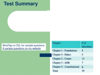
Summary of the test structure design. Grudiev 14/04/2010. 11.424 GHz, <100 MV/m>, 100 ns, reg. cells. CLIC_vg1: undamped damped. edms#1065638. edms#1065641. edms#1065642. 50%. 41%. 47%.

Summary of the test structure design
E N D
Presentation Transcript
Summary of the test structure design Grudiev 14/04/2010
11.424 GHz, <100 MV/m>, 100 ns, reg. cells CLIC_vg1: undamped damped edms#1065638 edms#1065641 edms#1065642 50% 41% 47% CLIC_G: undamped damped edms#1065640 edms#1065643 edms#1065646 18% 8% 13% A. Grudiev, 14/04/2010
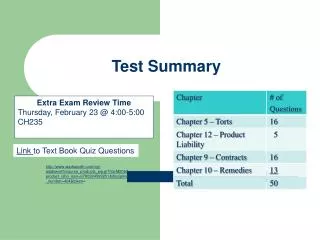
11.994 GHz, <100 MV/m>, 100 ns, reg. cells CLIC_G: undamped damped edms#1068314 edms#1070498 edms#1069239 17% 8% 8% new A. Grudiev, 14/04/2010
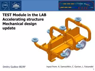
Preliminary Design of the Damping Load Will be used for CLIC module prototype and for a structure prototype for high power testing with damping load inside (TD24_vg1.8_diskR05_SiC) SiC properties from M.Luong, 1999 Tip size 1x1 mm Tip length 20 mm or 30 mm Base size 5.6 x 5 or 5.5 mm Base length 10 mm Waveguide width awd = 10.1 mm or 11 mm thick line: awg = 11mm, thin line: awg = 10.1 mm A. Grudiev, 14/04/2010
Design of the damped compact coupler Will be used for CLIC module prototype and for a structure prototype for high power testing with damped compact coupler (TD26_vg1.8_diskR05_CC) A. Grudiev, 14/04/2010
Beyond CLIC_G • A structure with a degree of tapering lower than TD18_vg2.6_disk (41%) and TD24_vg1.8_diskR05 (8%) is an interesting option • For example, ~ 20-25 % • It could also have bigger average aperture if CLIC main beam bunch charge can be increased accordingly. • A detailed optimization of the parameters and rf design will be done this year A. Grudiev, 14/04/2010
Direct comparison of variation of d Direct comparison of variation of P/c Direct comparison of variation of a and P/c Test for a relatively large group velocity The test matrix (all structures in disks) R. Zennaro 2008 In red: 11.4 GHz new structures (C10) In blue: 30 GHz new structures (scaled values for a and d) (C30) Damped version? (*) not very different from input vg1 (d=2.79; a=4.06)
C10 family • Aperture scan (un-damped cells) • C10_vg1.35 • C10_vg0.7 • Different damping geometry (damped cells with iris geometry from C10_vg1.35) • CD10_WDS • different materials are on hold • CD10_Choke (edms#1071742) • different choke gap will be investigated C10 family is still a valid approach because it is simpler and cheaper than a full scale tapered structure prototype. The main problem is lower priority so it goes very slow, much slower than tapered structures. (C10-paradox !) A. Grudiev, 14/04/2010
Single-feed mode launcher Design for C10 structures E-field H-field -40dB BW 90 MHz A. Grudiev, 14/04/2010
Quadrants/halves family HALVES Here T18_vg2.6_quad design is used. It has no slots. QUADs with SLOTS T18_vg2.6_Qslot design is used. It is the T18_vg2.6_quad but 4 slots of 0.2 mm rounded with 0.2mm radius are introduced. Corresponding frequency up-shift is ~1 MHz, well within tuning range. A. Grudiev, 14/04/2010