Download
1 / 30
310 likes | 368 Vues
Learn about different connecting devices in a network including passive and active hubs, bridges, switches, routers, gateways, and their functions. Understand backbone networks, bus and star topologies, connecting remote LANs, and more.

E N D
Chapter 15 Connecting LANs, Backbone Networks, and Virtual LANs
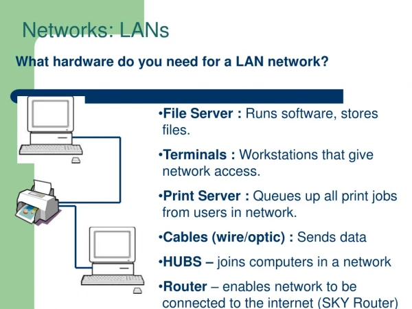
15-1 CONNECTING DEVICES In this section, we divide connecting devices into five different categories based on the layer in which they operate in a network. Topics discussed in this section: Passive Hubs Active HubsBridges Two-Layer Switches Routers Three-Layer Switches Gateways
Connecting Devices Figure 15.1 Five categories of connecting devices
Passive Hubs A passive hub is just a connector. It connects the wires coming from different branches. This type of a hub is part of the media; its location in the internet model is below the physical layer.
Repeater • Repeater only operates in the physical layer • Repeater regenerates the signal, and can extend the physical length. • Doesn’t connect two LANs, connects two segments of the same LAN
Repeater • A repeater connects segments of a LAN. • A repeater forwards every frame; it has no filtering capability • A repeater is a regenerator, not an amplifier.
Function of Repeater • Must be placed so that a signal reaches it before noise changes • the meaning of its bits
Active Hubs • Hub is a multiport repeater • Creates connections between stations in a physical star topology
Bridge • Bridge operates in both the physical and the data link layers • As a physical layer device, it regenerates the signal • As a data link layer device, it checks the physical (MAC) addresses • A bridge has a table used in filtering decisions.
Bridge Figure 15.6 A bridge connecting two LANs
Transparent - Bridge • A bridge does not change the physical (MAC) addresses in a frame. • Transparent Bridge • Bridge in which stations are completely unaware of the bridge’s existence • System equipped with transparent bridges must meet three criteria (IEEE 802.1d): • Frames must be forwarded from one station to another • Forwarding table is automatically made by learning from movements • Loops must be prevented
Learning - Bridge Figure 15.7 A learning bridge and the process of learning
Loop Problem Figure 15.7 Loop problem in a learning bridge
Spanning Tree • A spanning tree is a graph in which there is no loop. • In a bridged LAN, this means creating a topology in which each LAN can be reached from any other LAN through one path only (no loop).
Spanning Tree Figure 15.8 A system of connected LANs and its graph representation
Spanning Tree Figure 15.9 Finding the shortest paths and the spanning tree in a system of bridges
Forwarding ports and blocking ports • Dynamic algorithm – spanning tree algorithm is done dynamically with software in the bridge • using Bridge Protocol Data Unit (BPDU) Figure 15.10 Forwarding and blocking ports after using spanning tree algorithm
Bridges Connecting Different LANs • Bridge should be able to connect LANs using different protocols, issues to be considered: • Frame format – Ethernet vs. wireless frame • Max data size – too large fame must be fragmented into several frames and no protocol at the data link layer allows for fragmentation and reassembly of frames • Data rate – each LAN has its own data rate • Bit order – some send most significant bit first, some send least significant bit first • Security – wireless has security measures at the data link layer, Ethernet does not • Multimedia support – some support, some do not
Router Figure 15.11 Routers connecting independent LANs and WANs • A router is a three-layer device that routes packets based on their logical addresses (host-to-host addressing). • A router normally connects LANs and WANs in the internet and has a routing table that is used for making decisions about the route. • The routing tables are normally dynamic and are updated using routing protocols.
Gateway • A gateway is a normally a computer that operates in all five layers of the internet or seven layers of OSI model. • A gateway takes an application message, reads it, and interprets it. • This means that it can be used as a connecting device between two internetworks that use different models. • For example, a network designed to use the OSI model can be connected to another network using the internet model.
15-2 BACKBONE NETWORKS A backbone network allows several LANs to be connected. In a backbone network, no station is directly connected to the backbone; the stations are part of a LAN, and the backbone connects the LANs. Topics discussed in this section: Bus BackboneStar BackboneConnecting Remote LANs
Bus Backbone • In a bus backbone, the topology of the backbone is a bus. • Normally used to connect different buildings in an organization • Bridge blocks frames sent internal to the LAN • Backbone receives frame if going from one LAN to another
Star Backbone • In a star backbone, the topology of the backbone is a star; the backbone is just one switch. • Used as distribution backbone inside a building
Connecting remote LANs A point-to-point link acts as a LAN in a remote backbone connected by remote bridges.
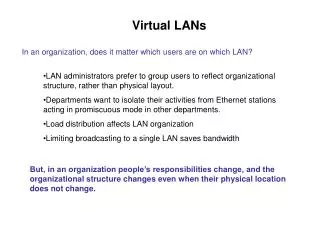
15-3 VIRTUAL LANs We can roughly define avirtual local area network(VLAN) as a local area network configured by software, not by physical wiring. Topics discussed in this section: MembershipConfiguration Communication between Switches
Virtual LANs Figure 15.15 A switch connecting three LANs
Virtual LANs Figure 15.16 A switch using VLAN software
Virtual LANs Figure 15.17 Two switches in a backbone using VLAN software
Summary • A repeater is a connecting device that operates in the physical layer of the Internet model. A repeater regenerates a signal, connects segments of a LAN, and has no filtering capability. • A bridge is a connecting device that operates in the physical and data link layers of the Internet model • A transparent bridge can forward and filter frames and automatically build its forwarding table. • A bridge can use the spanning tree algorithm to create a loopless topology. • A backbone LAN allows several LANs to be connected. • A backbone is usually a bus or a star. • A virtual local area network (VLAN) is configured by software, not by physical wiring. • Membership in a VLAN can be based on port numbers, MAC addresses, IP addresses, IP multicast addresses, or a combination of these features. • VLANs are cost- and time-efficient, can reduce network traffic, and provide an extra measure of security.