Advanced Methods in Materials Selection
Advanced Methods in Materials Selection. Conflicting Constraints Lecture 2 & Tutorial 2. IFB Lecture 2: Textbook Chapters 7 & 8. Conflicting Constraints. Fork for a pushbike: what is more important, strength or stiffness?. Stiffness dominated design versus Strength dominated design.

Advanced Methods in Materials Selection
E N D
Presentation Transcript
Advanced Methods in Materials Selection • Conflicting Constraints • Lecture 2 & Tutorial 2 IFB 2012 Conflicting Constraints
IFB Lecture 2: Textbook Chapters 7 & 8 IFB 2012 Conflicting Constraints
Conflicting Constraints Fork for a pushbike: what is more important, strength or stiffness? • Stiffness dominated design • versus • Strength dominated design IFB 2012 Conflicting Constraints
Outline Lecture 2 • Conflicting constraints: • “most restrictive constraint wins” • Case study 1: Stiff / strong / light tie rod • Case study 2: Safe (no yield - no fracture)/ light air tank for a truck IFB 2012 Conflicting Constraints
Most designs are over-constrained: “Should not deflect more than something, must not fail by yielding, by fatigue, by fast-fracture …” more constraints than free variables IFB 2012 Conflicting Constraints
Strong tie of length L and minimum mass Function Tie-rod F F Area A L Minimise mass m: m = A L (2) Objective • Length L is specified • Must not stretch more than Constraints Free variables • Material choice • Section area A Performance metric m1 E8.1. Materials for a stiff, light tie-rod Constraint # 1 m = mass A = area L = length = density E= elastic modulus = elastic deflection Equation for constraint on A: = L = L/E = LF/AE (1) Eliminate A in (2) using (1): Chose materials with largest M1 = IFB 2012 Conflicting Constraints
Strong tie of length L and minimum mass Function Tie-rod F F Area A L Objective (Goal) Minimise mass m: m = A L (2) m = mass A = area L = length = density = yield strength • Length L is specified • Must not fail under load F Constraints Eliminate A in (2) using (1): Free variables • Material choice • Section area A Chose materials with largest M2 = Performance metric m2 E8.1. Materials for a strong, light tie-rod Constraint # 2 Equation for constraint on A: F/A < y (1) IFB 2012 Conflicting Constraints
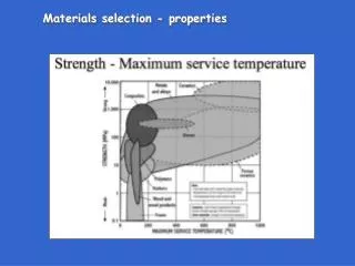
= deflection y = yield strength • E = elastic modulus Max. deflection Must not yield Competing performance metrics E8.1: Conflicting Constraints: Strong /Stiff / Light Tie Rod Requires stiffer material Evaluate competing constraints and performance metrics: Stiffness constraint Strength constraint Rank by the more restrictive of the two, meaning…? IFB 2012 Conflicting Constraints
Analytical solution in three steps: Rank by the more restrictive of the constraints 1. Calculate m1 and m2 for given L (1 m) and F (10 kN) 2. Find the largest of every pair of m’s 3. Find the smallest of the larger ones The most restrictive constraint requires a larger mass activeconstraint. Cons to the analytical solution: Solution is not general, as it is a function of L, δ and F. (I.e., the above solution represents only the particular values of L, δ and F used in the calculations.)Lacks visual immediacy. IFB 2012 Conflicting Constraints
mass /L= 0.1%:y constraint active (heavier) for short rods length Graphical version of the analytical solution (for Aluminium) /L= 0.1%:E constraint active (heavier) for long rods (rod stretches too much) IFB 2012 Conflicting Constraints
Pros to the graphical-analytical solution (Slide #10): it makes explicit the dependence on L and L/.Cons: it is specific to the material considered (requires a dedicated graph per material) Cons to the analytical solution (slide #9) (more restrictive constraint) Solution is not general, as it is function of L, δ and F Lacks visual immediacy. Graphical solution using indices and bubble charts: • More general/powerful. Changes in L, δ and F are easily visualised • Allows for a visual while physically based selection. • Involves all available materials. • Incorporates geometrical constraints through coupling factors. IFB 2012 Conflicting Constraints
M1 = M2= Graphicalsolution using Indices and Bubble charts This is what we know make m1= m2 Solve for M1 Straight line, slope = 1 y-intcpt = L/ IFB 2012 Conflicting Constraints
m1 = m2 E 8.1 Tie Rod Graphical solution (/L = 1% => L/ = 100) Use level 3, exclude ceramics Simultaneously Maximise M1 and M2 m1 < m2 Coupling line for L/ = 100 m2 < m1 IFB 2012 Conflicting Constraints
Coupling line for L/ = 1000 E8.1 Tie Rod Graphical solution( /L = 0.1% => L/=1000) Use level 3, exclude ceramics Active Constraint? 3-D view Coupling line for L/ = 100 IFB 2012 Conflicting Constraints
m1 = m2 lighter 3-D view of the interacting constraints m1 m2 m1 > m2 m2 > m1 Locus of coupling line depends on coupling factor • m1 = m2 on the coupling line. • The closer to the bottom corner, the lighter the component. • Away from the coupling line, one of the constraints is active (larger m) IFB 2012 Conflicting Constraints
lighter m1 = m2 Graphical solution (deflection = 1% L/=100) m1 < m2 Coupling line for L/ = 100 m2 < m1 IFB 2012 Conflicting Constraints
Compressed air tank Case Study # 2: Quite Similar to E8.2 (Tute 2), Air cylinder for a truck Design goal: lighter, safe air cylinders for trucks IFB 2012 Conflicting Constraints
t Density Yield strength y Fracture toughness K1c Pressure p 2R FunctionPressure vessel Objective Minimise mass ConstraintsDimensions L, R, pressure p, given Safety: must not fail by yielding Safety: must not fail by fast fracture Must not corrode in water or oil Working temperature -50 to +1000C Wall thickness, t; choice of material L Conflicting constraints lead to competing performance metrics Free variables Case study: Air cylinder for truck IFB 2012 Conflicting Constraints
t Density Yield strength y Fracture toughness K1c Pressure p 2R L Aspect ratio, Vol of material in cylinder wall Objective: mass Failure stress Stress in cylinder wall Safety factor Eliminate t transpose Air cylinder for truck What is the free variable? May be either y or f! IFB 2012 Conflicting Constraints
CES Stage 2: evaluate conflicting performance metrics: S = safety factor a = crack length y = yield strength K1c = Fracture toughness Must not yield: Must not fracture Competing performance metrics for minimum mass Air cylinder : graphical solution using CES charts CES Stage 1; apply simple (non conflicting) constraints: working temp up to 1000C, resist organic solvents etc. Equate m1 to m2, and find the coupling factor for given crack size a. IFB 2012 Conflicting Constraints
Max service temp = 373 K (1000C) Corrosion resistance in organic solvents Corrosion resistance Air cylinder - Simple (non- conflicting) constraints • CES Stage 1: • Impose constraints on corrosion in organic solvents • Impose constraint on maximum working temperature Select above this line IFB 2012 Conflicting Constraints
CES, Stage 2: Equate m1 to m2, and find the coupling factor for given crack size a. = = for a crack a = 5 mm, the coupling factor is 1/√(3.14*0.005) = 1/0.12 = 8 IFB 2012 Conflicting Constraints
Results so far: • Epoxy/carbon fibre composites • Epoxy/glass fibre composites • Low alloy steels • Titanium alloys • Wrought aluminium alloy • Wrought austenitic stainless steels • Wrought precipitation hardened stainless steels Lighter this way CES Stage 2: Find most restrictive constraint using Material Indices chart Air cylinder - Conflicting constraints a = 5 mm intcpt= 8 @ 1/M1= 1 Repeat for a = 5 μm IFB 2012 Conflicting Constraints
Summary • Most designs are over-constrained and many have multiple objectives • Method of maximum restrictiveness copes with conflicting multiple constraints • Analytical method useful but depends on the particular conditions set and lacks the visual power of the graphical method • Graphical method produces a more general solution • Next lecture will solve case studies for two conflicting objectives: e.g., weight and cost. IFB 2012 Conflicting Constraints
Solutions to E8.2 Exercises for Tutorial on multiple constraints • 8.2 a Coupling factor = 253 for c= 5 µm; • 8.2 b Coupling factor = 8 for c = 5 mm. 1- Textbook Exercise 8.2, p. 616 2- Exercise on slide # 27 IFB 2012 Conflicting Constraints
There is a typographical error in your textbook, Exercise E8.2,p. 616, 6 lines from the top It reads: It should read: IFB 2012 Conflicting Constraints
Exercise 2 for Tutorial on multiple constraints IFB 2012 Conflicting Constraints
Exercise 2 for Tutorial on multiple constraints • Hypothetical values to fix the coupling line IFB 2012 Conflicting Constraints
End of IFB Lecture 2 IFB 2012 Conflicting Constraints