Download
1 / 70
720 likes | 1.05k Vues
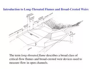
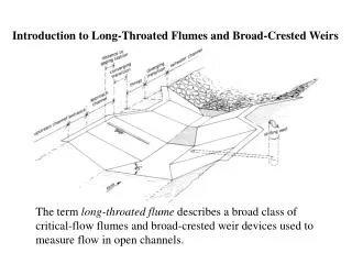
Introduction to Long-Throated Flumes and Broad-Crested Weirs. The term long-throated flume describes a broad class of critical-flow flumes and broad-crested weir devices used to measure flow in open channels. Critical-Flow Measurement Devices. Flumes, sharp-crested weirs, broad-crested weirs

E N D
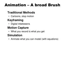
Introduction to Long-Throated Flumes and Broad-Crested Weirs The term long-throated flume describes a broad class of critical-flow flumes and broad-crested weir devices used to measure flow in open channels.
Critical-Flow Measurement Devices • Flumes, sharp-crested weirs, broad-crested weirs • Produce critical-depth flow in a control section • Froude number = V/(gD)1/2=1 • Critical depth occurs at locations where the downstream depth does not “hold the flow back” • Minimum specific energy for a given flow • Maximum flow for a given specific energy • Shallow-water waves cannot travel upstream • Tailwater does not affect headwater elevation • Flow rate through the critical section is a function of the upstream head, acceleration of gravity, and the control section size
Critical Depth • Specific energy
Critical Depth Thought Experiment A • Submerged weir in a channel with constant inflow • Initially submerged by high tailwater (downstream gate) • Lower the tailwater • Headwater lowers until we get flow through the weir with a minimum upstream depth • Minimum specific energy for a given flow
Critical Depth Thought Experiment B • Weir at outlet from infinite reservoir (depth constant) • Initially submerged by high tailwater (downstream gate) • Lower the tailwater (open the gate) • Discharge over weir increases until we get a maximum amount of flow over the weir • Maximum flow for a given specific energy
A B
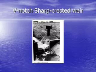
Traditional Critical-Flow Devices • Most critical-flow devices have curvilinear,three-dimensional flow fields in the control section • All such devices require laboratory calibration • Flumes • Parshall flumes, cutthroat flumes, H-flumes, etc. • Sharp-Crested Weirs • V-notch weirs, Cipoletti weirs, contracted and suppressed rectangular weirs, etc. • Broad-Crested Weirs • If they do not have a streamlined approach
Long-Throated Flumesand Broad-Crested Weirs • Long-throated flumes with a streamlined converging transition have one-dimensional flow in the control section -- Long-throated means long enough to eliminate lateral and vertical contraction of the flow at the control section…streamlines are essentially parallel • Can be calibrated using well-established hydraulic theory • No laboratory testing needed • Calculations are iterative, but computer models that do the calculations have made long-throated flumes reasonable to implement in recent years
Developing Rating Tables First, relate Q to yc as follows: • Guess a value of yc • Compute area, Ac, and top width, Bc, at critical section • Compute Q, and compute Hc
Developing Rating Tables Next, relate h1 to yc • Assume H1≈Hc • Solve iteratively for h1 using energy equation • Compute losses from 1 to c and revise: H1 = Hc+DH1 • Repeat until solution converges. We know H1 versus Q for a given value of yc.
Developing Rating Tables • Procedure as described yields Q and h1 values at specified increments of yc (irregular values of Q and h1) • Similar techniques can solve for Q at specified h1 or h1 at specified Q • Knowing Hc, we can also solve for H2 (highest allowable downstream tailwater) by subtracting DH2, the loss caused by expanding transition and exit channel friction
Submergence of Flumes and Weirs • h2/h1 is thesubmergence ratio • Sharp-crested weirs • NO SUBMERGENCEALLOWED • Parshall and other short-throated flumes • Some submergence allowed • Modular limit varies with flume size (50-80 percent) • Submergence correction needed when above modular limit (no longer a true critical-flow device)…even with correction, accuracy suffers, especially above 90 percent submergence
Submergence of Long-Throated Flumes and Broad-Crested Weirs • Location of critical section upstream from expanding transition makes it difficult to submerge the control section. • Gradual expansion (downstream ramp) can recover kinetic energy from control section • Highest modular limit (lowest head loss) of any critical-flow device • Modular limit varies, but can be predicted using WinFlume • Typically 80-90+ percent • No submergence correction needed as long as submergence is less than modular limit • Flow rate is always a function of ONLY the upstream water level
Long-throated flumes are the measurement device of choice for many applications. Advantages include: • Rating tables with error of less than 2% in the computed discharge can be computed for any combination of prismatic control section and an arbitrarily shaped approach channel • If the throat is horizontal in the direction parallel to the flow, accurate rating tables can be computed using as-built dimensions • Throat can be any shape in the direction perpendicular to the flow, allowing the complete range of discharges to be measured with good precision • Required head loss across the flumes is minimal • Long-throated flumes can be operated in free-flow with greater submergence than all other critical-flow devices, and the submergence limit (modular limit) and the associated head loss requirement can be determined using the WinFlume program • With properly constructed gradual converging transition, there is virtually no problem passing floating debris • Can be designed to pass sediment transported by channels having subcritical flow • Economical to construct • Very adaptable to installation in existing canals
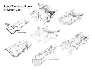
Stationary crest flume Movable crest flume
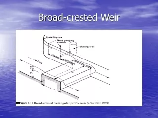
Approach Channel • Necessary for development of uniform and symmetric flow conditions in the control section • Establishes a stable upstream water surface whose elevation can be determined accurately • The approach channel may be lined or it may be the original earthen channel • Suggested length 2-3 times H1max from leading edge of control section, or H1max from beginning of converging transition, whichever is greater • Avoid drawdown area near control section, but also want to minimize head loss between gaging station and throat section
Gaging Station • Location at which we measure the upstream sill-referenced head. • Difference in elevation between the approach water level and the crest of the throat section • Flow rate through the flume will be computed as a function of the upstream sill-referenced head • Method of water level measurement affects total random error of flow measurement
Converging Transition • Provides for smooth acceleration of flow toward the throat with no discontinuities or flow separation • May consist of plane surfaces or may be rounded. Exact shape not critical for performance • Suggested length • Sufficient to produce bed slope of 2.5:1 or flatter • Sufficient to produce 2.5:1 or flatter side wall transition from approach channel to throat when viewed in plan
Components of Long-Throated FlumesThroat, Control Section, Crest/Sill, etc.
Throat or Control Section • Section in which flow passes through critical depth • Must be horizontal in the direction of flow • Can be any shape in direction perpendicular to the flow • Must be high enough to avoid submergence from downstream tailwater and to still flow in approach channel, but not so high that it encroaches upon freeboard in upstream channel • Must be wide enough to allow maximum flow to pass without encroaching on upstream freeboard, but narrow enough to produce a head that can be measured with reasonable accuracy
Throat or Control Section- Suggested Length - • 0.070 < H1/L < 0.70 for best accuracy • WinFlume’s rating tables will be accurate to better than 2% • 0.050 < H1/L < 1.0 is acceptable if measuring very wide ranges of flow (Qmax/Qmin > 100) • About 4% random error
Diverging Transition • Velocity of the supercritical flow exiting the throat section is reduced and energy is dissipated or partially recovered • If energy recovery is needed, a 6:1 downstream slope is recommended---can be truncated or full length • Full length allows for equipment passage • If energy recovery is not needed, the diverging transition can be eliminated
Tailwater Channel • Knowing water level in tailwater channel as a function of flow rate is fundamentally important to the design of the structure • Determines the elevation and size of the control section needed to maintain critical flow conditions in throat • For design, must know highest likely tailwater curve • May need energy dissipation and erosion control in tailwater section • Suggested length of protection for earthen tailwater channel is: • 4 times maximum depth • length of diverging transition • 5 feet
Principal Design Issues • Site • Uniform, fully-developed flow conditions approaching structure so that hydraulic theory is applicable • Flume control section • Ensure structure ponds water deep enough to stabilize upstream water surface for accurate measurement • Ensure that flume is not submerged by tailwater (contraction must be enough to force critical depth) • Ensure that flume does not create a “lack of freeboard” problem • Ensure that contraction produces enough head to make an accurate flow measurement • Component lengths must meet “long-throated” criteria
Uniform Approach Flow • Channel should be straight and have reasonably uniform cross-section for a length equal to approximately 30 times the upstream head • If there is a bend closer to the structure, the water surface elevations at the two sides of the channel will be different. • Reasonably accurate measurements can be made (added systematic error about 3%) if the upstream straight channel has a length equal to about 2 times its width • Water level should be measured on side corresponding to inside of bend
Smooth Water Surface • Approach channel Froude number, Fr1, should not exceed 0.5 over a distance of at least 30 times h1 upstream from the structure • If feasible, reduce the Froude number to 0.2 within the approach section to the flume • Distance to any upstream structures that discharge highly turbulent water (e.g. undershot gates, drop structures) should be more than 20 times the water surface width at maximum flow
Ensure Critical Depth • Contracted throat section of flume will raise upstream water surface unless flume can be installed at an existing drop in canal • Head loss needed to obtain critical depth can be determined by WinFlume • Diverging transition can reduce required head loss • Knowing the upstream head and required head loss, maximum allowable tailwater level can be determined • The modular limit is the ratio h2/h1 at maximum allowable tailwater level
Upstream Effects • If no drop in the channel bottom is available to accommodate the head loss required for critical flow in the control section, the flume will cause a rise in the upstream water level • May reduce the freeboard in the upstream channel • May reduce the head available over upstream structures, which could reduce their discharge capacity • May need to do backwater analysis in channel upstream of flume to evaluate this problem
Flow Measurement Accuracy • Rating tables for long-throated flumes have a ±2% discharge uncertainty when computed using WinFlume • Head-measurement error adds additional uncertainty • Percentage error in head measurement is large when trying to measure a very small head • Flume should have enough contraction so that we can measure the head with a low percentage error
Lengths of Flume Components • Throat section length, L 0.07<H1/L<0.7 for ±2% uncertainty 0.05<H1/L<1.0 for ±4% uncertainty • Floor and sidewalls of converging transition 2.5 to 4.5:1 transition slope • Diverging transition No flatter than 10:1 • Gaging station location (approach channel length) > H1 upstream of start of converging transition (2 to 3) * H1max from start of throat
Constructability Range of Flows to be Measured Throat Section Shape Selection
Typical Flume/Weir Configurations • Sill in a concrete-lined canal • Rectangular-throated flumes for earthen canals • Triangular-throated flumes for natural channels • Flumes in circular pipes • Portable and temporary flumes
Poor construction detail. Abrupt changein channel cross section between gage and critical section.