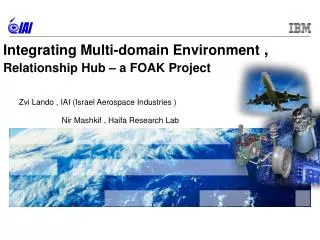
Integrating Multi-domain Environment , Relationship Hub – a FOAK Project
390 likes | 536 Vues
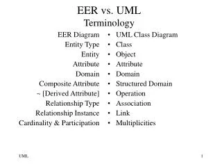
Zvi Lando , IAI (Israel Aerospace Industries ) Nir Mashkif , Haifa Research Lab. Integrating Multi-domain Environment , Relationship Hub – a FOAK Project. Agenda. Integrated NPI: Hierarchical System View. System Engineer. System Engineer. System Engineer. System Engineer.

Integrating Multi-domain Environment , Relationship Hub – a FOAK Project
E N D
Presentation Transcript
Zvi Lando , IAI (Israel Aerospace Industries ) Nir Mashkif , Haifa Research Lab Integrating Multi-domain Environment , Relationship Hub – a FOAK Project
Integrated NPI: Hierarchical System View System Engineer System Engineer System Engineer System Engineer System Engineer System Engineer System Engineer System Engineer System Engineer System Engineer System Engineer System Subs 1 Subs 2 Subs 3 Mod 1.1 Mod 1.2 Mod 2.1 Mod 2.2 Mod 2.3 Mod 3.1 Mod 3.2 SW Comp HW Comp Mech Comp SW Comp HW Comp Mech Comp
Integrated NPI: Inter-Discipline View Systems Engineering Process Software Engineering Process Electronics Engineering Process System Engineer System Engineer System Engineer System Engineer System Engineer System Engineer System Engineer System Engineer System Engineer System Engineer Mechanical Engineering Process Inter-Node Process Alignment & Data Continuity Inter-Node, Inter-Discipline, Process Alignment & Data Continuity Intra-Node, Inter-Discipline, Process Alignment & Data Continuity
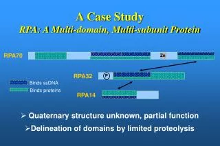
Integrated NPI: Example Air Vehicle Control Station Mission Planning Station Portable Video Terminal Air Frame Avionics Payload Payload Control (Software) Payload Equipment (Electronics) Payload Structure (Mechanics) Search And Rescue Automated Helicopter SARAH Requirements Cross-Discipline Constraints Structural Constraints
Business Objectives Reduce Time Reduce Cost Improve Quality E n a b l e Integrated Development Environment
Integrated Development Environment Process Alignment Data Continuity Tool Connectivity
Example: Requirements Engineering & Test Design Data Continuity Data duplication Requirements Engineering Process System Requirements DOORS (IBM) System Requirements Derivation Test Design Process Quality Center (HP) Test Design Specialized Connector Manual or no notification of availability Notification of System Requirements availability for test design Process Alignment 8
Data Continuity Challenges Mentor, SAP… Challenge 3: Extend to additional tools SA ,RPE Other:SAP - ERP Mantor Harness Doors HP Quality Center TCUE /NX Rhapsody Mantra Challenge 1: Avoid building & maintaining multiple specialized inter-tool connectors Challenge 2: Avoid inter-tool data duplication 9 9
Agenda 10
Traceability • Product data exists in different systems SA RPE Doors • Impact analysis Relationship Hub HP Quality Center TC /NX Rhapsody PDM • Data Duplication • DataContinuity The Relationship Hub -The Solution Approach • No peer to peer integration 11 11
“TO BE” Environment P2P tools/Systems environment tools/Systems with Relationship Hub 12
Clearcase/RTC SA Rhapsody DOORS PDM TC/Mantra TC/NX Capabilities of the Relationship Hub • RelationshipHub: • Support Systems Engineering Method • Cross tool models/artifacts integrated view • Cross tool models/artifacts bidirectional relations • Cross tool search and query • Impact analysis • Inter Connectivity rules checking via constraint satisfaction technology • Cross tool reports and documents generation • Cross domain baselining Wiring/ messaging Reports/ RPE 13
The Relationship Hub Architecture Build on - CAM Manufacturing /ERP SE: SystemArchitect , Rhapsody Req: Doors Testing: HP QC SW: Rhapsody ,RSA Mechanical Eng: Team Center PDM tool: ALM / PLM RH Adapter RH Adapter RH Adapter RH Adapter RH Adapter RH Adapter WPS SOA/OSLC bridge REST APIs RH Web UI Relationship Hub Apps: • Impact analysis • Inter Connectivity Rule Checking – By CSP solver • Document Generation – By RPE • Bi directional Inter Link Creation and mgt RH UI Extensions in ALM/PLM Tools REST APIs Jazz Team Server Data Model C Data Model B Data Model A 14
Cross Tool Models/Artifacts Integrated View Impact Analysis IRC – Interconnectivity Rule Checking Automatic Document Generation The Relationship Hub Applications 15
SA DOORS TC/NX Cross Tool Models/Artifacts Integrated View RelationshipHub Inter Links • Integrated view of data models from heterogeneous engineering tools • Stores only indexing data including intra-relationships • Capture client methodology for enriching the data • Enable query the data according to the client methodology • Cross tool relations among model elements from different tools/disciplines • Common Web UI for create and manage Inter Relations Intra Links 16
SA DOORS TC/NX Impact Analysis • The ability to identify all related elements that could potentially be impacted by a change in an Elements • Perform smart search across RH elements and relations according to predefine types: • Upstream impact analysis • Downstream impact analysis • Customize – reflects the customer’s analysis definitions • Uses advance visualization • Modify the results , navigation, aggregations ,comments • Present and aggregate the result according to the customer reference model (e.g. system /Sub systems) RelationshipHub 17
Structural view is not enough and not reflect the real systems structure IAI’s preferred to arrange the results according to their system and sub system structure The RH system enables flexible way to define additional custom views. (e.g. Functional view) Impact Analysis – Reference Model Systems/Sub System Elements Impact analysis – Systems decomposition view 18
Interconnectivity Rules Checking (IRC) DesignProcess Methodology RH Existing items and links Rules on links structure Extendable to a model which satisfies rules ? • CSP solver • NP Complete • Declerative no yes • Implicit links • Forbidden links • Allowed links Violations and Contradictions 19
Requirements coverage by tests A test covers a requirement Requirement must be associated to a single model element (or is defined non-functional) A test is derived from a single function If a test covers a requirement, it must be derived from the function which is linked to the same requirement Example requirement associated cover test function derive 20
Documents Generation in Heterogeneous Environment Generates composite document with diverse data sources whose relationships are managed by Relationship Hub. Siemens TCU System Architect Systems Modeling Rational Publishing Engine Document Generation DOORS Requirement Management SA Diagram DOORS Requirement HP QC SA Definition (4) Send composite view , Generate Document (3) Send data for creating views (1) Publish data for creating links Relationship Hub Compose comprehensive view (2) Create links Relationship Model Maintain relationship model 21
Agenda 22
Integrated NPI: Example Air Vehicle Control Station Mission Planning Station Portable Video Terminal Air Frame Avionics Payload Payload Control (Software) Payload Equipment (Electronics) Payload Structure (Mechanics) Search And Rescue Automated Helicopter SARAH Requirements Cross-Discipline Constraints Structural Constraints
Integrated Systems Engineering Environment 1. Derive System Requirements Systems Tests System (SARAH) Requirement Verification Allocation Integration Subsystem (AV) Subsystem Tests Requirement Verification Integration Allocation Module (PYLD) Module Tests Requirement Verification Integration Allocation End Component (PYLD Strct) End Component Tests Req’ Verification 25
Deriving system requirements • Challenge: • Associate requirements in DOORS with model elements in SA without having to copy model elements from SA into DOORS DOORS Problem Terms Analysis Solution Terms Merged Stakeholder Reqs System Reqs Trace System Architect Associate M_Modes M_Activities M OM1 P P S S C1 M_Modes OMm Cn Q Q OMm R P R P CN 26
Relationship Hub UI for Creating Links DOORS element 2. Select a start element using the dialog box 1. Press Locate Element to specify a start element of the link to be created 1. Create Link within Doors DOORS-SA link SA element 4. Select an end element of the link using the dialog box 5. A link between the start and end elements is create 3. Press Create to create a link 27
Cross Tool Documents Generation Using RPE Generates an SSS [System Specification] with the new integration architecture DOORS RelationshipHub SystemArchitect GeneratedSSS DOORS DXL REST API REST API SA Diagram ModifiedSSSTemplate SA Definition RPE DOORS Requirement Generates 28
Generated Document“System Requirement Coverage” From QC From DOORS System requirements from DOORS and associated QC tests are arranged in a tabular form. Their relationships are defined in the Relationship Hub. 29
Snapshot of a RPE Generated Document Data from DOORS Data from TC
Use case: Integrated Systems Engineering Environment 7. Change Impact Analysis Systems Tests System (SARAH) Requirement Verification Allocation Integration Subsystem (AV) Subsystem Tests Requirement Verification Integration Allocation Module (PYLD) Module Tests Requirement Verification Integration Allocation End Component (PYLD Strct) End Component Tests Req’ Verification 31
Stake Holder requirement Adjustable Camera changes “Camera elevation shall be adjustable from pointing straight down to 15 degrees above the horizon” “Camera elevation shall be adjustable from pointing straight down to 17 degrees above the horizon” Change in Stake Holder requirement What are the elements impacted as a result of this change? 32
Impact Analysis UI [1/6] Trigger the Impact analysis from with in the tools set 33
Impact Analysis UI [2/6] Structural view 34
Impact Analysis UI [3/6] System View 35
Impact Analysis UI [4/6] System view – Expand SARAH 36
Impact Analysis UI [5/6] System view – Expand Air Vehicle 37
Impact Analysis UI [6/6] System view – Expand Payload 38