Download
1 / 32
360 likes | 709 Vues
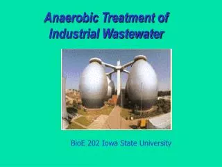
ENVIRONMENTAL BIOTECHNOLOGY Anaerobic Treatment. Chapter 3 Lecturer Dr. Kamal E. M. Elkahlout Assistant Prof. of Biotechnology. Anaerobic basics Anaerobes flourish in the complete absence of dissolved oxygen. They use oxygen in the combined state as in nitrate and sulphate

E N D
ENVIRONMENTAL BIOTECHNOLOGYAnaerobic Treatment Chapter 3 Lecturer Dr. Kamal E. M. Elkahlout Assistant Prof. of Biotechnology
Anaerobic basics • Anaerobes flourish in the complete absence of dissolved oxygen. • They use oxygen in the combined state as in nitrate and sulphate • Biogas (= methane + carbon dioxide) is a product of anaerobiosis whereas aerobic processes produce no biogas. • Anaerobic treatment is relatively cheap because of its • i. Low operating costs. ii. Less sludge production • iii. Low space requirements. iv. High biogas production
Principles of anaerobic wastewater treatment • Anaerobic wastewater treatment is the biological treatment without the use of air or elemental oxygen. • Many groups of anaerobic bacteria “work” together in the absence of oxygen to degrade complex organic pollutants into methane and carbon dioxide (biogas). • Their microbiology is more complex and delicate. • In aerobiosis aerobes work individually to decompose organic matter. • Anaerobiosis involves a number of chain reactions each being performed by a specific and specialized bacteria.
Hydrolysis (conversion of solids into liquids), Acidogenesis (acid production) • Acetogenic (acetate building) and Methanogenic (methane formation) phases are most common. • Methane bacteria use acetic acid, (H2) & (CO2) to generate (CH4).
COD Balance • Organic pollution is measured by the weight of oxygen it consumes to oxidize pollutants chemically. • This weight of oxygen is referred to as the “chemical oxygen demand” (COD). • The difference between anaerobic wastewater treatment and aerobic wastewater treatment in its COD balance is shown in fig. 5.4.
Advantages of Anaerobic Treatment Processes • Less energy required: Anaerobic process requires less energy compared to aerobic process. • Less biological sludge production: As it involves less energy less biomass production occurs requiring less volume for storage. • Fewer nutrients required: Aerobic process needs more nutrients (as N, P, K) to treat industrial wastes. • Their quantity is much less for anaerobic processes because less biomass is produced. • Higher volumetric loadings: Aerobic processes are designed for an organic loading of 0.5 to 3.5 kg COD/cu.m.d whereas it is 3.5 to 35 kg COD/m3.d for anaerobic processes.
DisAdvantagesof Anaerobic Treatment Processes • i. Anaerobiosis is relatively a slow process compared to aerobiosis. • ii. Anaerobes are more sensitive to toxic compounds than aerobes. • iii. The products of biological decomposition are more odourous, corrosive and less stable. • iv. Anaerobiosis operates in a narrow pH range and can not tolerate higher acidity (even that induced because of CO2 production) • v. Need for alkalinity addition: The most significant negative factor that can affect the economics of anaerobic verses aerobic treatment is need to add alkalinity.
Alkalinity of 2000 to 3000 mg/l (as CaCO3) may be needed in anaerobic processes to overcome the acidity induced because of CO2 production during the decomposition. • Applications of Anaerobic Treatment • Anaerobic processes are used with advantage to treat concentrated liquid organic wastewaters of distillery, brewery, pulp and paper manufacturing and petrochemical industries. • At higher temp., (as in tropics) even dilute waste (as domestic sanitary sewage) can be treated efficiently. • Anaerobic treatment processes include anaerobic suspended growth, upflow and down flow anaerobic attached growth, fluidized bed attached growth, upflow anaerobic sludge blanket reactor (UASB) etc.
Anaerobic suspended growth process • When no media exists within the reactor for the microbes to settle but are carried along with the wastewater flow (i.e. when the microbes are in suspended state within the wastewater) it is called Suspended Growth Processes. • Three types of anaerobic suspended growth treatment processes are: • i. The complete mix suspended growth anaerobic digester • ii. The anaerobic contact process and • iii. The anaerobic sequencing batch reactor • (i) Complete mix process: In this process the contents of the tank are intimately mixed so that fresh incoming wastewater gets intimately mixed with the old wastewater undergoing decomposition so that a homogeneous mix is obtained.
For the complete mix anaerobic digester, the hydraulic(detention) retention and solids retention time (SRT) are equal. • The retention time may be from 15 to 30 days depending on temperature and nature of wastewater. • The complete mix digester without sludge recycle is more suitable for concentrated wastes with high concentrations of organic solids. • Here no chance exists for the sludge to get separated from the wastewater as the contents are intimately mixed and no stratification can take place. • (ii) Anaerobic contact process: The anaerobic contact process overcomes the disadvantages of a complete mix process without recycle.
Biomass is separated and returned to the complete mix or contact reactor so that the process SRT is longer than hydraulic retention time, therefore the anaerobic reactor volume can be reduced. • (iii) Anaerobic sequencing batch reactor (ASBR): • The ASBR is a suspended growth process of four stages (i) feeding (ii) reacting (mixing) (iii) settling and (iv) decanting and effluent withdrawal. • A critical feature of the ASBR process is the settling velocity of the sludge during the settling period before decanting the effluent. • Settling times used are about 30 min within the same reactor.
Upward Flow Anaerobic Sludge Blanket System (UASB): • It consists of a rectangular or cylindrical tank of 4 to 5 m of liquid depth. • Raw wastewater subjected to screening and grit removal (but without primary sedimentation) is admitted at the bottom of this tank and made to flow upwards at a velocity of 0.15 to 0.3 mm/sec. • Its (plan) area is so designed to maintain a retention time of 8 to 10 hours. • The wastewater rises up and millions of sludge particles rising up held in suspension form the base for the anaerobes to rest and degrade the organic matter. • It takes 30 to 90 days (depending on the ambient temperature) for the sludge blanket to get formed and acclimatized and the efficiency of the system increases with time.
(It takes less time if the seeding is done by initially loading the reactor with sludge washout from another reactor in working condition with good efficiency). • Biogas is collected at the top. • Scum accumulated at the top is removed once in 2 or 3 years and this is to facilitate free flow of gas. • The tank is emptied once in 5 to 7 years to improve efficiency. • For effective functioning of the system the pH is to be kept neutral and slightly on the alkaline side. • The ratio of concentration of volatile fatty acids to that of alkalinity should never fall below 1:2 and if it falls below 0.5 it can be improved by the addition of bicarbonate alkalinity.
UASB design consideration • 1. UASB is designed where temperature of the reactor is usually between 20 °C to 25 °C. • 2. Solids retention time is 30 to 50 days • 3. Hydraulic retention time is 8 to 10 hours • 4. Depth: 4.5 to 5 m (for domestic sewage) • 5. Width or diameter: 10 to 12 m • 6. Sludge blanket depth: 2 to 2.5 m (for domestic sewage) • 7. Surface flow rate: 20 to 28 m3/m2/d at peak flow • 8. Upflow velocity: 0.1388 mm/sec at average flow and 0.333 mm/sec at peak flow
Reactor volume & dimensions • To determine the required reactor volume and dimensions, the organic loading, velocity of flow, and effective treatment volume are to be considered. • The effective treatment volume is that occupied by the sludge blanket and active biomass. • Some more volume exists between the sludge space and gas space in which zone the biomass is dilute, and sedimentation of solids is relatively less. • Organic loading rate is given by
where Vn = effective (nominal/sludge blanket) liquid volume of reactor, m3 • Q = rate of flow, m3/day • So = influent COD, kg/COD/m3 • Lorg = organic loading rate, kg COD/ m3.d • Total liquid volume of the reactor is given by
Septic Tanks • Septic tanks are used for the treatment of wastes from scattered, isolated and individual houses. • It may be regarded as a downward flow sludge blanket system. • The septic tank is an anaerobic treatment plant where (i) settling of solids (ii) floatation of grease (iii) anaerobic decomposition of organic matter and (iv) anaerobic digestion of sludge take place. • A septic tank is a combined sedimentation cum digestion tank. • The removal of settleable solids and the anaerobic digestion of these solids are taking place simultaneously. • The tank is kept completely covered at the top with a provision of a high vertical vent for the escape of the gases.
Gases such as methane, carbon dioxide, and hydrogen sulphide are released during the digestion process. • The effluent contains considerable BOD and at times may be more than that of the influent. • The effluent contains considerable amount of dissolved and suspended putrescible organic solids and viable pathogens. • The effluent must be treated before letting off into natural open drains or natural courses of water. • It is disposed of either by sub-surface irrigation or into soak pits. • Due to anaerobic digestion of sludge and consequent release of gases, appreciable reduction in the volume of sludge takes place.
Adequate storage capacity must be provided so that the deposited sludge remains in the tank for a sufficient length of time to undergo digestion before being withdrawn. • In general, sludge should be removed once in every 3 to 5 years. • Design considerations • 1. Shape: Generally rectangular • Minimum length = 1.5 m • Minimum breadth = 0.75 m • L : B = 2 : 1 or 3 : 1 or 4 : 1 • Liquid depth = 1.2 to 2.5 m
2. Detention period: 24 hours (most common) it ranges from 8 to 48 hours depending on the ambient temperature • 3. Sludge contribution: 75 /capita/year • 4. Minimum volume: 3 m3 • 5. Free board: 0.5 m • 6. Bottom slope: 5 to 10% • 7. Ventilation stack: > 50 mm in diameter
Attached growth anaerobic process • Upflow attached growth anaerobic treatment reactors can be further classified based on the type of packing used and the degree of bed expansion. • (i) Upflow packed bed attached growth reactor: They are similar to trickling filters as far as the media is concerned. The packing material can be broken stone or plastics. • However, they are only 2 to 8 m in diameter. • The media is always submerged with wastewater as the flow is upwards. • While the microbes of trickling filter rest on the medium, most of the microbes of upward flow attached growth anaerobic process is loosely held in the void space of packing space.
While its depth is 3 to 13 m as in trickling filters, media packing may extend through the full depth or may just get confined to the top 50 % to 70% of the depth. • The organic loading rate is relatively high i.e. 1 to 6 kg (COD)/m3.d. • Most common operational problem is getting clogged because of voids getting filled up. • Flushing is done to remedy the situation. • So, this process is best suited to treat wastewaters with less suspended solids.
(ii) Upflow attached growth anaerobic expanded bed reactor (AEBR): • In this reactor very fine media as sand (0.2 to 0.5 mm) is used instead of broken stone. • Sand being finer, offers more surface area (to support microbes) for the same volume of broken stone. • However, sand when soaked under water undergoes expansion. When this expansion is 20% or less sand still retains the properties of the medium and hence called Expanded bed reactor. • (iii) Attached growth anaerobic fluidized bed reactor (FBR): • When sand undergoes 100% expansion it behaves as a fluid and hence called fluidized bed reactor. Its working principle is the same as AEBR. It is designed for an upward flow of 5.55 mm/sec.
The tank may have a depth of 4 to 6 m. • Activated carbon or other similar adsorbing media (0.6 to 0.8 mm in dia) may be used instead of fine sand. FBR can take an organic loading rate of 10 to 20 kg (COD)/m3.d. • The advantages for the anaerobic FBR process include the ability to provide high biomass concentrations and relatively high organic loadings, high mass transfer characteristics, the ability to handle shock loads due to its mixing and dilution with recycle and minimal space requirements.


![[:environmental biotechnology :]](https://cdn1.slideserve.com/1605269/slide1-dt.jpg)