Download
1 / 27
480 likes | 881 Vues
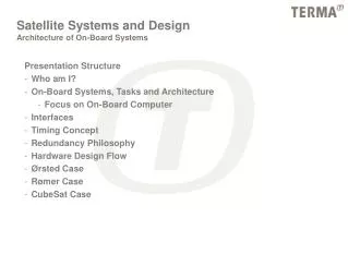
Satellite Systems and Design Architecture of On-Board Systems. Presentation Structure Who am I? On-Board Systems, Tasks and Architecture Focus on On-Board Computer Interfaces Timing Concept Redundancy Philosophy Hardware Design Flow Ørsted Case Rømer Case CubeSat Case.

E N D
Satellite Systems and DesignArchitecture of On-Board Systems Presentation Structure • Who am I? • On-Board Systems, Tasks and Architecture • Focus on On-Board Computer • Interfaces • Timing Concept • Redundancy Philosophy • Hardware Design Flow • Ørsted Case • Rømer Case • CubeSat Case
Architecture of On-Board SystemsWho am I? Name: Peter Davidsen Age: 32 Education: Civilingeniør E, 1993, DTU Experience: 8 years in the Space Industry • Ørsted subsystem designer (CPD) • Ørsted systems engineer • Test and validation • Launch and Operation • Rømer lead systems engineer (Platform) • Terma Star Tracker lead systems engineer Contact, and don’t hesitate to do so!!!! pd@terma.com
Architecture of On-Board SystemsOn-Board Systems, Tasks and Architecture Satellite on-board systems • Functions indicated • How shall these functions be implemented? • How shall they be linked together? (Interfaces) • What kind of tasks are assigned to each function?
Architecture of On-Board SystemsOn-Board Systems, Tasks and Architecture Electrical Power Subsystem (EPS) • Power Control and Distribution Unit (PCDU) • Solar panel(s) • Battery (peak power, orbit eclipse) PCDU • Solar panel(s) and battery management (BCR or MPPT) • Centralized or de-centralized DC/DC converters • User switches and protection • Housekeeping and protection • Control and OBC interface • AUX converter (internal power supply)
Architecture of On-Board SystemsOn-Board Systems, Tasks and Architecture On-Board Computer • Command and Data Handling (CDH) • Receive, process and distribute telecommands from ground • Collect science data • Collect housekeeping and report telemetry • Telemetry storage in mass memory • Forward telemetry to ground • Satellite autonomous control and monitoring (e.g. safe mode, time tagged commands...) • Timing reference and correlation • Autonomous attitude control • etc. e.g. Star tracker data processing, Payload data processing…..
Architecture of On-Board SystemsOn-Board Systems, Tasks and Architecture OBC Core and Memory • Core • Central processor • System clock • Watchdog • Memory and interrupt control • DMA, if needed • Memory • Boot memory • Non-volatile memory • System and mass memory • EDAC • Single event upset mitigation (Hamming coding) • Power interface
Architecture of On-Board SystemsOn-Board Systems, Tasks and Architecture OBC Peripheral Units • Interface unit 1..n • Debug interface • Master time-base and timer functions • Housekeeping circuit (V, I, T) • Discrete signal handling (I/O) • TCP and external events • Latch-up protection (not shown)
Architecture of On-Board SystemsOn-Board Systems, Tasks and Architecture
OBC Key Problem Areas Processor selection Performance (MIPS and FLOPS) Power consumption Space environment Tools Memory Technology (e.g. EEPROM/FLASH, SRAM/DRAM…) Power consumption Size (bytes) Space environment Protection Interface implementation UART or FPGA FPGA selection (for space) Timing and peak load Protocol selection (high and low level) Test Exercise: identify possible processors for the use in CubeSat OBC Architecture of On-Board SystemsOn-Board Systems, Tasks and Architecture
Architecture of On-Board SystemsOn-Board Systems, Tasks and Architecture OBC for CubeSat? • Consider using a PIC controller • PC104 ‘standard’, www.pc104.com • Consider ‘reverse engineering’ • Look for LOW POWER and extended temperature range. • or simply GET INSPIRED! Problem area: Not qualified for Space, but might be used by others?
Attitude Control Subsystem (ACS) ACS SW part of OBC Sensors Star tracker Rate sensors Magnetometer Sun sensors Earth horizon sensors Determine sensor configuration Select I/F to OBC HW Low and high level protocols Actuators Momentum/Reaction wheels Magnetorquer coils/rods Permanent magnet Thruster Libration Damper Determine actuator configuration Select I/F to OBC HW Low and high level protocols Architecture of On-Board SystemsOn-Board Systems, Tasks and Architecture
Communication subsystem (COM) Receiver (Rx) LNA Down converter, IF amplifier Demodulator Transmitter (Tx) Modulator Solid state power amplifier (SSPA) Duplex filter (one Rx/Tx antenna) Antenna (S-band, VHF, UHF) Controller OBC interface Rx/Tx mode control Up/down link protocol handling either in COM or OBC Coding and decoding Housekeeping Essential V, I, T and Rx/Tx status Power control and interface Architecture of On-Board SystemsOn-Board Systems, Tasks and Architecture
Architecture of On-Board SystemsInterfaces Interface Types • Electrical (HW) • Functional (SW) • Mechanical • Thermal all this MUST BE SPECIFIED FOR ALL SUBSYSTEMS
Architecture of On-Board SystemsData Interfaces • Configuration • Star • Bus • Type • Serial • Parallel • Timing • Asynchronous • Synchronous • Control • Master-Slave (MS) • Master-Master (MM) Exercise: List advantages and drawbacks of the Bus and Star configurations
Architecture of On-Board SystemsData Interfaces • Typical interfaces • RS422 (Star, serial, async/sync, MS/MM) • RS485 (Bus, serial, async, MS/MM) • PASTE (Star/Bus, parallel, sync, MS) • CAN (Bus, serial, async, MM) • Mil-Std-1553 (Bus, serial, async, MM) • ….. • Avoid using to many I/F configurations and types !!!!! Exercise: CubeSat interface brainstorming
Architecture of On-Board SystemsData Interfaces Interface Protocol • High level • Application layer • Low level • Data link layer • Physical layer
Architecture of On-Board SystemsData Interfaces • High level, e.g. Packet Utilization Standard • Low level, e.g. CAN, radio link • Note, some I/F standards include only electrical properties (e.g. RS422 and RS485), other also low level protocol (e.g. CAN and 1553). Protocol standards • Use a standard low level protocol on the up/down link • Re-use ground station • Use standard or non-standard between OBC and SUS
Architecture of On-Board SystemsData Interfaces Data Flow Analysis • Inter Satellite (OBC to subsystems) • Ground/Satellite link • Ground data distribution • Interface bandwidth requirements including up/down link • Interface peak loads • OBC mass storage (if implemented)
Architecture of On-Board SystemsTiming Concept • Relative time correlation • OBC to subsystem • Absolute time correlation • OBC to GPS • OBC to Ground • Both principles rely on local time stamping of the signal “pulse”, followed by interchange of timestamp.
Architecture of On-Board SystemsRedundancy Philosophy Introduction to Redundancy • Redundancy is used to increase satellite/subsystem reliability • Redundancy can be applied on: • system level • subsystem level (e.g. two OBCs, interface cross-coupling) • subsystem internal (e.g. double boot PROMs) • Redundancy can be implemented as ‘hot or cold’ • Typical problems when introducing redundancy • increase in system complexity + mass, power and volume • will the reliability be increased at all? • test • cost
Architecture of On-Board SystemsRedundancy Philosophy Redundancy Roadmap • Baseline minimum configuration that satisfies the mission requirements • Evaluate reliability of each subsystem for a give lifetime and orbit • Evaluate complexity of making a subsystem redundant • Evaluate cost of making a subsystem redundant • Then decide • Hot or Cold? • Interface cross strapping? • Other constraints: mass, volume, power etc. decide on redundancy concept Exercise: CubeSat = Single String why?
Architecture of On-Board SystemsHardware Design Flow HW design, step-by-step • Input • High level tasks • Radiation environment (given the orbit, lifetime and epoch) • Max power, mass, envelope etc. • External interface requirements • Power and data • Output • Specification • Component selection • Architectural design • Detailed design
Architecture of On-Board SystemsRømer Case Note: • Single String Satellite • Single Payload • CDH Combines: • Command and Data Handling • ACS Computer • Star Tracker Computer • ‘Intelligent’ COM, EPS and Payload • Common Data Bus (CAN) • Easy Test Access • ‘Simple Subsystems’ accessed through PDU
Architecture of On-Board SystemsCubeSat Case CubeSat Block Diagram • Gray boxes indicate ‘need to be’ • 2’nd priority • Battery • Payload sensor • ACS actuator • ACS sensor(s) • No direct redundancy • OBC tasks • C&DH • Up/Down link protocol handling • ACS data processing • PCDU high level control • Payload data processing
CubeSat, recommendation Limit you ambitions! 1 Payload Keep it simple! Is ACS necessary? Keep constant track of engineering budgets (mass, power, volume) Implement a simple satellite safe mode: Radio beacon Non essential loads OFF Make it possible to change OBSW Use simple COM (amateur radio) UHF/VHF, COTS unit Standard protocol Use a centralized DC/DC converter Include battery (peak power) Consider deployable solar panels Due to the tight engineering budgets COTs components/subsystems (e.g. PC104 as OBC) Pay attention to the thermal design Use simple interfaces AND simple protocols. Implement a direct access debug interface to the OBC used during ground tests Test, Test and Test Architecture of On-Board SystemsCubeSat Case