Download
1 / 66
670 likes | 718 Vues
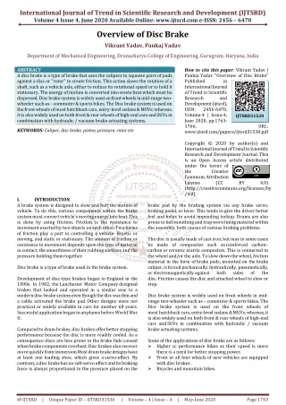
Discover disc brake diagnosis and service advice, from pad wear to caliper inspection, to ensure efficient vehicle braking systems. Learn how to identify and address brake system issues.

E N D
102 DISC BRAKE DIAGNOSIS AND SERVICE
TECH TIP: Let the Owner Drive When verifying the customer complaint, ask the owner or driver of the vehicle to drive. Often, the problem is best discovered if the vehicle is being driven exactly the same way as when the complaint first occurred. For example, the technician may brake harder or softer than the driver so the problem may not be detected.
Figure 102-1 Minimum thickness for various types of disc brake pads. Pad wear sensors often make a “chirping” sound when the vehicle is moving if the pads are worn. Do not confuse that noise for a defective wheel bearing or other fault.
Figure 102-2 This cracked disc brake pad must be replaced even though it is thicker than the minimum allowed by the vehicle manufacturer and the wear sensor was not close to the rotor.
Figure 102-3 Be careful to observe the direction in which replacement linings are facing. Some vehicle manufacturers offset the friction material on the steel backing to help prevent or minimize tapered pad wear. Check service information for details as to which direction the pads should be installed.
Figure 102-4 Most disc brake calipers have a brake inspection opening. For a thorough inspection, however, the caliper should be removed and the entire braking system thoroughly inspected.
TECH TIP: The Bleed and Squirt Test If you suspect a brake is not being fully released, simply loosen the bleeder valve. If brake fluid squirts out under pressure, then the brake is being kept applied. Look for a defective flexible brake hose. If the vehicle is off the ground, the wheels should be able to be rotated with the brakes off. If a wheel is difficult or hard to turn by hand and is easy to turn after opening the bleeder valve, then there is a brake fluid restriction between the master cylinder and the brake.
Figure 102-5 (a) Both rear- and forward-mounted calipers have the bleeder valve at the top. Some calipers will fit on the wrong side of the vehicle, yet not be able to be bled correctly because the bleeder valve would point down, allowing trapped air to remain inside the caliper bore. If both calipers are being removed at the same time, mark them “left” and “right.”
Figure 102-5 (b) Both rear- and forward-mounted calipers have the bleeder valve at the top. Some calipers will fit on the wrong side of the vehicle, yet not be able to be bled correctly because the bleeder valve would point down, allowing trapped air to remain inside the caliper bore. If both calipers are being removed at the same time, mark them “left” and “right.”
Figure 102-6 Many manufacturers recommend removing one-half of the brake fluid from the master cylinder before servicing disc brakes. Use a squeeze bulb and dispose of the used brake fluid properly.
Figure 102-7 Most manufacturers recommend that the bleeder valve be opened and the brake fluid forced into a container rather than back into the master cylinder reservoir. This helps prevent contaminated brake fluid from being forced into the master cylinder where the dirt and contamination could cause problems.
Figure 102-8 Many calipers use a hollow “banjo bolt” to retain the flexible brake line to the caliper housing. The fitting is usually round like a banjo. The copper washers should always be replaced and not reused.
Figure 102-9 Caliper retaining bolts are often called guide pins. These guide pins are used to retain the caliper to the steering knuckle. These pins also slide through metal bushings and rubber O-rings.
Figure 102-10 If the caliper is not being removed, it must be supported properly so that the weight of the caliper is not pulling on the flexible rubber brake line. A suitable piece of wire, such as a coat hanger, may be used.
Figure 102-11 A wooden block or a folded shop cloth helps prevent damage when caliper pistons are removed. Use extreme care when removing a caliper piston using compressed air. The pressure applied can force the piston out of the caliper with tremendous force. Always follow service information instructions.
Figure 102-12 After the piston is removed from the caliper housing, the dust boot can often be removed using a straightblade screwdriver.
Figure 102-13 Phenolic (plastic) pistons should be carefully inspected.
REAL WORLD FIX: Three Brake Jobs in 40,000 Miles A service technician was asked to replace the front disc brake pads on a Pontiac Grand Am because the sensors were touching the rotors and making a squealing sound. This was the third time that the front brakes needed to be replaced. Previous brake repairs had been limited to replacement of the front disc brake pads only. When the caliper was removed and the pads inspected, it was discovered that a part of one pad had broken and a piece of the lining was missing. - SEE FIGURE 102–15.Then the technician spotted something at the rear of the vehicle that told the whole story—a trailer hitch. The owner confirmed that a heavy jet ski was towed in hilly terrain. The technician recommended overhauling the front disc brake calipers to prevent the possibility of the front pads dragging. The technician also recommended an inspection of the rear brakes. The rear brakes were glazed and out-of-adjustment. The technician received permission to replace the rear brakes, overhaul both front calipers, and install quality disc brake pads. When the customer returned, the technician advised the customer to use the transmission on long downhill roads to help keep the brakes from overheating and failing prematurely.
Figure 102-14 If there are any surface flaws such as rust pits on the piston, it should be replaced.
Figure 102-15 These pads were found to be cracked and a section was missing from a part of one pad.
Figure 102-16 Removing the square-cut O-ring seal from the caliper bore. Use a wooden or plastic tool to prevent damage to the seal groove.
Figure 102-17 Some manufacturers recommend cleaning the inside of the caliper bore using a honing tool as shown. Even though the caliper piston does not contact the inside of this bore, removing any surface rust or corrosion is important to prevent future problems. If the honing process cannot remove any pits or scored areas, the caliper should be replaced.
Figure 102-18 Installing a new piston seal. Never reuse old rubber parts. A caliper overhaul kit includes just two items: the square-cut piston seal O-ring and dust boot.
Figure 102-19 Brake assembly fluid or clean brake fluid from a sealed container can be used to lubricate the caliper seal and caliper pistons before assembly.
Figure 102-20 Installing the caliper piston. Many calipers require that the dust boot be installed in the groove of the piston and/or caliper before installing the piston.
TECH TIP: Using “Loaded Calipers” Saves Time Many technicians find that disassembly, cleaning, and rebuilding calipers can take a lot of time. Often the bleeder valve breaks off or the caliper piston is too corroded to reuse. This means that the technician has to get a replacement piston, caliper overhaul kit (piston seal and boot), plus the replacement friction pads and hardware kit. To save time (and sometimes money), many technicians are simply replacing the old used calipers with “loaded calipers.” Loaded calipers are remanufactured calipers that include (come loaded with) the correct replacement friction pads and all the necessary hardware. - SEE FIGURE 102–26 . Therefore, only one part number is needed for each side of the vehicle for a complete disc brake overhaul.
Figure 102-21 Installing a piston into a caliper. Sometimes a C-clamp is needed to install the piston. Both the piston and the piston seal should be coated in clean brake fluid before assembly.
Figure 102-22 Seating the dust boot into the caliper housing using a special plastic seating tool.
Figure 102-23 All rubber bushings should be lubricated with silicone brake grease for proper operation.
Figure 102-24 (a) Using a screwdriver to force the outboard pad into proper position before bending the retaining tabs.
Figure 102-24 (b) Use two hammers to bend the tab where it extends through the hole in the caliper body.
Figure 102-25 Often, a hammer is necessary to bend the retainer flange to make certain that the pads fit tightly to the caliper. If the pads are loose, a “click” may be heard every time the brakes are depressed. This click occurs when the pad(s) move and then hit the caliper or caliper mount. If the pads are loose, a clicking noise may be heard while driving over rough road surfaces.
Figure 102-26 A loaded caliper includes all hardware and shims with the correct pads all in one convenient package, ready to install on the vehicle.
Figure 102-27 Floating calipers must be able to slide during normal operation. Therefore, there must be clearance between the caliper and the caliper mounting pads (abutments). Too little clearance will prevent the caliper from sliding and too much clearance will cause the caliper to make a clunking noise when the brakes are applied.
Figure 102-28 Using an air-powered sanding disc to clean the caliper mount pads.
Figure 102-29 Determine which face of the special tool best fits the holes or slots in the piston. Sometimes needle-nose pliers can be used to rotate the piston back into the caliper bore.
Figure 102-30 Note the twisted flexible brake line. This was caught by an automotive instructor before the brake work on the vehicle was completed. The twisted brake line can cause brake hose failure if not corrected.
TECH TIP: Always Double-Check Your Work Whenever reassembling brakes, it is easy to twist the flexible brake hose as shown in - FIGURE 102–30 . To prevent possible brake hose failure and possibly an accident, always double-check that the ribs on the brake hose are straight. The ribs allow the service technician to easily spot if the hose has been twisted.
TECH TIP: Increasing Pad Life Many vehicles seem to wear out front disc brakes more often than normal. Stop-and-go city-type driving is often the cause. Driving style, such as rapid stops, also causes a lot of wear to occur. The service technician can take some actions to increase brake pad life that are easier than having to cure the driver’s habits. These steps include the following. 1. Make sure the rear brakes are properly adjusted and working correctly. If the rear brakes are not functioning, all of the braking is accomplished by the front brakes alone. NOTE: Remind the driver to apply the parking brake regularly to help maintain proper rear brake clearance on the rear brakes. 2. Use factory brake pads or premium brake pads from a known manufacturer. Tests performed by vehicle manufacturers show that many aftermarket replacement brake pads fail to deliver original equipment brake pad life.
Figure 102-31 For best braking performance, purchase replacement disc brake pads that include all clips and shims specified by the vehicle manufacturer. Some pads even come with a package of the specified grease to use on the shims to reduce the possibility of brake noise.
CHART 102–1 The causes of brake noise can have many reasons and corrections.
Figure 102-32 Notice the beveled pads. The shape of the pad helps reduce brake noise.
TECH TIP: The Screwdriver Trick A low brake pedal on GM vehicles equipped with rear disc brakes is a common customer complaint. Often the reason is a lack of self-adjustment that should occur whenever the brake pedal (or parking brake) is released. During brake release, the pressure is removed from the caliper piston and the spring inside the caliper piston is free to adjust. Often this self-adjustment does not occur and a low brake pedal results. A common trick that is used on the vehicle assembly line is to use a screwdriver to hold the piston against the rotor while an assistant releases the brake pedal. - SEE FIGURE 102–33 . As the brake pedal is released, the adjusting screw inside the caliper piston is free to move. Sometimes, it may be necessary to tap on the caliper itself with a dead-blow hammer to free the adjusting screw. Repeat the process as necessary until the proper brake pedal height returns. If this method does not work, replace the caliper assembly.
TECH TIP: The Screwdriver Trick (cont.) In summary, recall these steps. STEP 1 Have an assistant depress the brake pedal. STEP 2 Using a screwdriver through the hole in the top of the caliper, hold the piston against the rotor. NOTE: Be careful not to damage the dust boot. STEP 3 While still holding the piston against the rotor, have the assistant release the brake pedal. The adjusting screw adjusts when the brake pedal is released and a slight vibration or sound will be noticed as the brake is released. This vibration or sound is created by the self-adjusting mechanism inside the caliper piston taking up the excess clearance. STEP 4 Repeat as necessary until normal brake pedal height is achieved.
Figure 102-33 The screwdriver blade is used to keep the piston applied to allow self-adjustment to occur when the brake pedal is released.
TECH TIP: Pressure Testing Can Help Find Problems A stuck caliper or caliper slide is often difficult to see or diagnose as a problem because the movement of the broken pads is so little. Using a pressure gauge between the caliper piston and the rotor (inboard) or between the rotor and the caliper (outboard) can tell the service technician if there is a difference between the left and the right side brakes. - SEE FIGURE 102–34 .
Figure 102-34 (b) The small “pads” can be placed between the caliper piston and the rotor to check for applied pressure and inserted between the caliper and the rotor on the outside of the rotor to test the pressure—the pressure should be the same if the caliper is able to slide on its pins or slides.
DISC BRAKE SERVICE 1 After properly setting the hoist pads under the vehicle, raise the vehicle to chest level and remove the lug nuts.
DISC BRAKE SERVICE 2 Remove the wheel/tire assembly and place it where it will not get in the way or be damaged.