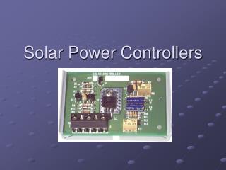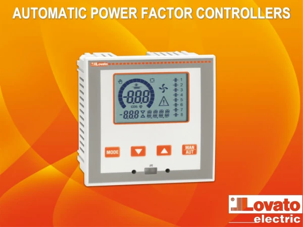
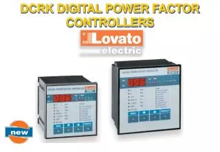
DCRK DIGITAL POWER FACTOR CONTROLLERS
DCRK DIGITAL POWER FACTOR CONTROLLERS. DCRK DIGITAL POWER FACTOR CONTROLLERS. 96X96mm. 144X144mm. DCRK5 5 steps DCRK7 7 steps. DCRK8 8 steps DCRK12 12 steps. DCRK DIGITAL POWER FACTOR CONTROLLERS. OPERATING FEATURES. MEASUREMENTS. Present cos j Present L-L voltage + maximum

DCRK DIGITAL POWER FACTOR CONTROLLERS
E N D
Presentation Transcript
DCRK DIGITAL POWER FACTOR CONTROLLERS 96X96mm 144X144mm • DCRK5 5 steps • DCRK7 7 steps • DCRK8 8 steps • DCRK12 12 steps
DCRK DIGITAL POWER FACTOR CONTROLLERS OPERATING FEATURES MEASUREMENTS • Present cosj • Present L-L voltage + maximum • Present current + maximum • Dkvar e kvar • Weekly average P.F. and present P.F. • Capacitor overload % + maximum • Present panel temperature + maximum . Measurement logged in non-volatile memory and keypad clearable.
DCRK DIGITAL POWER FACTOR CONTROLLERS OPERATING FEATURES BUILT-IN PROTECTIONS • Capacitor current overload • Capacitor over-voltage • Panel over-temperature • No-voltage release.
DCRK DIGITAL POWER FACTOR CONTROLLERS OPERATING FEATURES SETUP • Base setup with most common settings • (6 parameters) • Advanced setup with special settings • (16 parameters) • Fast PC setup • Fully automatic setup
DCRK DIGITAL POWER FACTOR CONTROLLERS OPERATING FEATURES ALARMS • A01 Under-compensation • A02 Over-compensation • A03 Low current • A04 High current • A05 Low voltage • A06 High voltage • A07 Capacitor overload • A08 High temperature • A09 No voltage release.
DCRK DIGITAL POWER FACTOR CONTROLLERS ADVANTAGES • Extensive number of measurements • (V-A- kvar- ecc.) • Capacitor overload protection • Measurement of weekly average power • factor • Built-in temperature sensor • TTL/RS-232 serial communication interface • Manual or Automatic set-up • Programmable alarms • Automatic identification of CT current flow • Easy CT setting for the final user • Measurement of power factor as well as • cosj • Keypad lock function.
DCRK DIGITAL POWER FACTOR CONTROLLERS CERTIFICATIONS cULus (UL for USA and Canada) COMPLIANCE IEC61010-1; IEC/EN 61000-6-2; CISPR 11/EN 55011
DCRK DIGITAL POWER FACTOR CONTROLLERS COMPARISON
DCRK DIGITAL POWER FACTOR CONTROLLERS COMPARISON
DCRK DIGITAL POWER FACTOR CONTROLLERS COMPARISON
DCRK DIGITAL POWER FACTOR CONTROLLERS TECHNICAL SPECIFICATIONS TRMS = TRUE ROOT MEAN SQUARE DCRK measurements are calculated in TRMS, to give exact values also in presence of harmonic distortion.
DCRK DIGITAL POWER FACTOR CONTROLLERS TECHNICAL SPECIFICATIONS COSj= DISPLACEMENT POWER FACTOR It is in the cosine of the displacement angle between voltage and current. DCRK regulators can read correctly the D.P.F. regardless of the presence of harmonics on current and voltage waveforms.
DCRK DIGITAL POWER FACTOR CONTROLLERS TECHNICAL SPECIFICATIONS POWER FACTOR The Power Factor (P.F.) or Total Power Factor (TPF) is the ratio between active power (W) and apparent power (VA). In a system without harmonics, the power factor is the same value as COSj. In other conditions, the power factor is less than the COSj. Power factor correction systems can adjust the COSj to the required value and can thereby obtain the best possible power factor. W W P.F. = P.F. = VA VA
DCRK DIGITAL POWER FACTOR CONTROLLERS Wh Wh P.F. = Varh² + Wh² Varh² + Wh² TECHNICAL SPECIFICATIONS MEASUREMENT OF WEEKLY AVERAGE POWER FACTOR This reading considers the last 7 days of the DCRK operation. It is calculated in the same way used by energy suppliers, storing active and reactive energy meters in DCRK internal memory. This value is therefore a true efficiency index of the entire reactive power correction system.
DCRK DIGITAL POWER FACTOR CONTROLLERS TECHNICAL SPECIFICATIONS AUTOMATIC IDENTIFICATION OF CT CURRENT FLOW At power up, the DCRK controller automatically recognizes the current flow direction through the Current Transformer (CT). This avoids inverting the CT connections during installation. In cogeneration plants, where it is necessary to operate in 4-quadrant, the CT connection sense must be set manually.
DCRK DIGITAL POWER FACTOR CONTROLLERS TECHNICAL SPECIFICATIONS EXTREME REDUCTION OF STEP SWITICHING A control algorithm provides for the maximum reduction of the number of operations. The adjustment is conducted in a precise manner and not by consecutive attempts. The reduction of the number of operations substantially lowers the capacitor and contactor wear.
DCRK DIGITAL POWER FACTOR CONTROLLERS TECHNICAL SPECIFICATIONS HOMOGENEOUS USE OF EQUAL RATED STEPS Each step is provided with one operation counter and one hour meter, in order to provide an equal usage of capacitors with the same rating. The uniform operation of the steps prolongs the life and efficiency of both the capacitors and contactors.
DCRK DIGITAL POWER FACTOR CONTROLLERS TECHNICAL SPECIFICATIONS AUTOTRIMMING Consents to the ongoingcontrol of the steps power installed. In case of step wear, all the relative power parameters are automatically recalculated. This allows the DCRK unit to work rapidly and efficiently, that is with fewer and quicker operations.
DCRK DIGITAL POWER FACTOR CONTROLLERS TECHNICAL SPECIFICATIONS 5% 5th HARM U THD = 5% CAP OVRL = 102.5% OVERLOAD PROTECTION OF CAPACITORS The capacitor overload can be caused by overvoltage or, more often, by non-linear loads that cause harmonic distortion on the voltage line. The voltage waveform is analysed by special algorithm that calculates the exact percentage of the current flowing in the capacitors. Once the set current overload threshold limit is exceeded, the capacitors are disconnected within a time inversely proportional to the exceeding limit. THD (Total Harmonic Distortion) does not change with harmonic frequency, and therefore it is not an indicator of capacitor overload. 5% 7th HARM U THD = 5% CAP OVRL = 105.5% 5% 11th HARM U THD = 5% CAP OVRL = 114.5% 5% 13th HARM U THD = 5% CAP OVRL = 120%
DCRK DIGITAL POWER FACTOR CONTROLLERS TECHNICAL SPECIFICATIONS NO VOLTAGE RELEASE This function can prevent damage to the capacitors by disconnecting them from the mains when short power lossess are detected.
DCRK DIGITAL POWER FACTOR CONTROLLERS TECHNICAL SPECIFICATIONS PROTECTION AGAINST OVER-TEMPERATURE The DCRK controllers include an internal temperature sensor, which monitors the temperature variation of the electric panel. This temperature value isdisplayed and the maximum value is logged. By setting related parameters, a threshold can be set to switch on a relay to operate a ventilation system. It is also possible to set an higher threshold to generate an overtemperature alarm.
DCRK DIGITAL POWER FACTOR CONTROLLERS G M TECHNICAL SPECIFICATIONS FOUR-QUADRANT OPERATION When a plant is equipped with a co-generation system, it means there are conditions where energy is imported (consumed) and others where it is exported (generated). In these circumstances, the displacement angle between voltage and current can vary between 0° and 360° (four quadrants) so the DCRK must be programmed accordingly. It is possible to set two independent cosφ setpoints, one for imported and the other for exported energy. When working with cogeneration plants, automatic CT connection feature cannot be used.
DCRK DIGITAL POWER FACTOR CONTROLLERS TECHNICAL SPECIFICATIONS EASY CURRENT TRANSFORMER SETTING The manufacturer of power factor correction panels can set all of the setup parameters of the DCRK except the CT primary, since it depends on the final customer plant. In this case, during the system installation and once the controller is powered up, the display will show a flashing CT indicating thatthe CT has not been programmed. Just selecting the correct value from the list and storing it with one key will enable the DCRK operation.
DCRK DIGITAL POWER FACTOR CONTROLLERS TECHNICAL SPECIFICATIONS AUTOMATIC SETUP Allows the installation of the DCRK controllers without programming any parameter. Just pushing two keys, the user is able to put the DCRK into operation. 5sec
DCRK DIGITAL POWER FACTOR CONTROLLERS TECHNICAL SPECIFICATIONS KEYPAD LOCK • The activation of this function is made by a combination of keys. • Once programmed, the following operations will be locked: • Access to parameter setup • Changing of COSj setpoint • Changing the operating mode (AUT/MAN) • MAX values clearing • However, all the measurements will be still accessible. 1° MODE 2° 3 x 3° 2 x
DCRK DIGITAL POWER FACTOR CONTROLLERS TECHNICAL SPECIFICATIONS TTL / RS-232 INTERFACE By using the DCRK SW software and the TTL/RS-232 interface, a quick set-up of the controller can be achieved via PC, avoiding in this way, possible parameter setting errors. The DCRK programmed parameters can also be stored on the PC and quickly downloaded into an unlimited number of units, which require the same programming. The customising of alarm properties can be made as well as the automatic panel testing with the control of the power installed and the test report printing too.
DCRK DIGITAL POWER FACTOR CONTROLLERS DCRK SW SOFTWARE TTL / RS-232 COMMUNICATION PORT • Full system monitoring: • - Graphic and numeric • measurements display • - DCRK status • - Virtual front panel • For each step: • - Function • - Status • - Reactive power • - Operation counter • - Hour meter.
DCRK DIGITAL POWER FACTOR CONTROLLERS DCRK SW SOFTWARE MONITORING THE CAPACITORS EFFICIENCY • Counter for the number • of switching operations • of each capacitor step. • Time counter for the • total connection time • of each capacitor step. • Measurement of the • actual kVar of each • capacitor step.
DCRK DIGITAL POWER FACTOR CONTROLLERS DCRK SW SOFTWARE TTL / RS-232 COMMUNICATION PORT • Access to all setup parameters in four languages • Save / Load / Print parameters • Highlighted user changes • Back-to-default button.
DCRK DIGITAL POWER FACTOR CONTROLLERS DCRK SW SOFTWARE TTL / RS-232 COMMUNICATION PORT • Alarm properties customization • - Alarm enable • - Alarm relay activation • - Step disconnection • - Alarm trip delay.
DCRK DIGITAL POWER FACTOR CONTROLLERS DCRK SW SOFTWARE TTL / RS-232 COMMUNICATION PORT • Automatic testing of • electric panel.
DCRK DIGITAL POWER FACTOR CONTROLLERS Kvar (400V) 60 60 50 45 38 40 30 30 20 15 20 12,5 8 10 Contactor BF12K BF25K BF20K BF65K BF40K BF50K BF80K BF9K SPECIAL POWER FACTOR CORRECTION CONTACTORS
DCRK DIGITAL POWER FACTOR CONTROLLERS SPECIAL POWER FACTOR CORRECTION CONTACTORS KITS TO ASSEMBLE BF..K CONTACTORS
DCRK DIGITAL POWER FACTOR CONTROLLERS Other products for your power factor correction system Push buttons and selectors Switch disconnectors Digital multimeters
THANK YOU AND GOODBYE www.LovatoElectric.com