Download
1 / 45
480 likes | 681 Vues
Routing and the IP v4 Address Space. BSAD 141 Dave Novak Sources : Network + Guide to Networks, Dean 2013. Outline. Routing How routers work Routing tables Static and Dynamic routing IP address space overview. Routing. Routers

E N D
Routing and the IP v4 Address Space BSAD 141 Dave Novak Sources: Network+ Guide to Networks, Dean 2013
Outline • Routing • How routers work • Routing tables • Static and Dynamic routing • IP address space overview
Routing • Routers • Can translate between different data link layer protocols and can connect dissimilar networks • Ethernet to token ring • Why can’t “basic” cut through switches connect dissimilar networks?
Routing • Basic functionality at Layer 3 of OSI • Forwards packets from source LAN to destination LAN • If LANs are not adjacent, the router forwards packets to another router, and so on until the router associated with the destination LAN is reached • On an internetwork (or the Internet), packets typically traverse many routers • Each router exchange is referred to as a “hop”
Routing versus switching • Generalization: Routing manages packet flow between different networks (or subnets) while switches manage packet flow withinnetworks (or subnets)
Routers and Gateways • Router/Gateway is a term used in TCP/IP • Default gateway (Layer 3) • Application gateway (Layer 7)
Routers • Routers are selective with respect to forwarding packets • Do not forward broadcasts • Work with IP datagrams (at layer 3) • Routers have routing tables, which contain addressing information about networks around it • Send packets directly to destination router OR simply forwards packets to “best” router
Routing – packet switching concept Internet Data are divided into packets Each packet may take a different route to destination 3 LAN 2 10 LAN Destination 5 Source 11 1 6 9 7 8
1 2 B 5 4 1 1 3 A C 2 6 3 2 8 1 2 1 4 D E 3 2 Routing logic Simplified routing example for Router A Example network A, B, C, D, E – a router 1, 2, 3 – a port on a router Red number – cost on link 137.99.105.98 145.85.99.101
Internet routing • On a small internetwork a router simply forwards packets destined for remote network to that network • Separate local traffic from remote traffic • On larger, more complex internetworks, the router must select the “best” or most efficient path from source to destination • Often measured by fewest hops
Routing tables • All TCP/IP devices have some type of routing table • A table to determine where to send packets • MAC address mapped to IP address • Systems store local address mappings and can usually transmit local packets directly to the receiving system • Systems typically use a default address (the IP address of an edge router) for non local transmission
Routing tables List of networks (and maybe hosts) and addresses of the other routers that a system will use to reach them
Internet routing • Routers populate their routing tables with destination IP address and best route info • Two broad categories of routing • 1) Static – routes that do not change • Network admin creates table manually • 2) Dynamic – system changes routing table information over time • Router uses routing protocols to exchange information with routers around it to learn optimal routes to different destinations
IP datagram • Size of IP datagram payload is not fixed • The sending application selects payload of datagram • Why is a variable IP datagram payload important in the context of WAN/internetworking usage?
IP datagram v4 • IP Datagram header contains IP addresses • IP Datagram can contain • Min of 1 byte excluding header • Max of 65,535 bytes including header • IP Datagram header is fixed size • 20 bytes • Contains IP address of sender • IP address of receiver
IP datagram • http://www.inetdaemon.com/tutorials/internet/ip/datagram_structure.shtml
MTU and datagram size • Max amount of data one frame can carry is specified by each separate networking technology (layer 2) • Limit is know as maximum transmission unit (MTU) • Network hardware will not accept frames larger than MTU • Token ring frames don’t work with Ethernet hardware – not only are addressing schemes different, TR frames are much larger than Ethernet frames
MTU and datagram size • Review: IP Datagram needs to fit into payload area of every type of frame • Why? • How?
MTU and datagram size • Different hardware will specify different MTUs • Token ring (802.5) frame • Max size 4500 Bytes • Ethernet (802.3) frame • Max size 1526 Bytes • ATM frame • Max size 53 Bytes
Fragmentation • Breaking up or subdividing datagram • Router divides original IP datagram into smaller pieces called fragments and routes each fragment separately • IP fragments are packaged into frames (like other data)
Reassembly • Process of re-creating copy of original IP datagram from fragments is called reassembly
Identifying datagram • Since IP does not guarantee delivery (IP provides best-effort, connectionless service), we have a potential problem • Fragments can be lost or arrive out of order • How can packets arrive out of order? • Is this common?
Identifying datagram • How are fragmented datagrams tracked? • Unique ID number for each IP datagram • When datagram is fragmented, ID number is copied into each fragment • Receiver can use ID number + IP source address to reconstruct fragment • A separate field in IP datagram header provides fragment order
Fragment loss • IP is connectionless – possible to lose fragments • When individual fragments arrive at destination, they are stored in memory until entire datagram can be reconstructed • If entire datagram cannot be reconstructed, all fragments are discarded • A timer is set by the receiving computer once the first fragment arrives. • If all fragments arrive before timer expires, the timer is stopped and the host reassembles the datagram • If not, fragments are discarded
IPv4 addressing scheme • Unique 32-bit number • Contains both IP address for source and destination • You have to know the IP address of the recipient to contact remote host • Use DNS to map URL to remote host IP address • IP address divided into 2 parts • Prefix – the network identifier • Suffix – the host identifier
IP Address Assignments • Every device on a network (or subnet) must have • The same network identifier as the other devices on the network (or subnet) • A unique host identifier to differentiate between each and every device on that network
IP Address Assignments • The Internet Assigned Numbers Authority (IANA) assigns network identifiers (http://www.iana.org/), but you typically obtain network addresses from an Internet Service Provider (ISP) • Prefix (network ID) assigned globally • Network administrators assign host identifiers • Suffixes (host ID) assigned locally
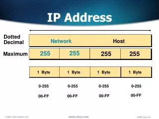
IPv4 addresses • Dotted decimal –way that humans view IP addresses • 137.99.101.22 • Binary – the way hardware/software reads addresses • 10001001.01100011.01100101.00010110 • 4 separate octets divided by a dot or period • An octet = Byte • Each octet contains 8 bits
The IP address decomposed 32-bit – comprised of 4 separate 8-bit parts 137.99.101.22 10001001.01100011.01100101.00010110 • 10001001 = 137 This represents an octet One “octet” – 8 bits each bit can EITHER be a zero or one All bits in network ID and host ID CANNOT be set to 0 or 1 0 and 255 are NOT valid network addresses or valid host addresses
IP addresses decomposed We have 256 possible values for each octet • 28 = 256 • The values are 0 – 255 • The octet 00000000 = 0 • The octet 11111111 = 255 8 bits in each octet – 8 possible choices Working with base 2 numbering system
IP addresses decomposed • Decompose 137.99.101.22
Classes of IP addresses • There are different classes of IP addresses • Determined by how many octets in prefix and how many in suffix • IPv4 addresses have 32 total bits – 4 octets • How octets are allocated between prefix / suffix • IP addresses divided into 3 primary classes where each class has a different size prefix and suffix
Classes of IP addresses • Classes A, B, and C are primary classes • Used for host addresses • Class D is used for multicast • The class is determined by boundary between the network prefix and the suffix
Classes of IP addresses All IPv4 addresses have 32 TOTAL bits – 4 octets with 8 bits in each octet. The class determination dictates where the boundary between the network portion and the host portion of address is drawn.
Classes of IP addresses • You can tell which class by the first few bits • Class A – 1st bit always = 0 • 01100101 • Class B – first bit always = 1, second bit always = 0 • 10111101 • Class C – first 2 bits always = 1, third bit always = 0 • 11000011
Classes and dotted decimal Any value in range ALWAYS will have “0” as first bit Any value in range ALWAYS will have “10” as first two bits Any value in range ALWAYS will have “110” as first three bits Example: Class A – 119.x.x.x = 01110111 Example: Class B – 190.x.x.x = 10111110 Example: Class C – 200.x.x.x = 11001000
Division of address space • IP address scheme doesn’t divide 32-bit address space into classes of equal size • For example, class A, B, and C do NOT have the same number of addresses • Half of ALL IP addresses lie in class A networks, but class A can only contain 126 networks
Subnets • As the Internet grew, original class-based addressing scheme proved insufficient • The IPv4 class-based addressing scheme is very inflexible • The choice of network class (size) is limited to either A, B, or C • So, networks support fixed number of hosts: • A) 16.77 million hosts / network • B) 65,534 hosts / network • C) 254 hosts / network
Subnets • Subnetting or classless addressing allows division of boundary between suffix and prefix • Effectively add more unique addresses within a given class • More efficient allocation of addresses • Provides additional flexibility within class-based addressing • Administrators can “shift” or move the boundary between suffix and prefix
Subnet masks • Subnetting requires the use of an additional piece of information called a subnet mask • 32-bit value that specifies boundary between suffix and prefix • Can change the class boundary • Specifies which bits of an IP address are the network ID and which are the host ID • The 1 bits are the network identifier bits • The 0 bits are the host identifier bits
Default subnet masks For class B, the first two octets represent the network ID – leaving the last two octets for host identification
Summary • Routing • How routers work • Routing tables • Static and Dynamic routing • IP address space overview (most of lecture focuses on IPv4 address space, address decomposition, and subnetting