Download
1 / 16
170 likes | 323 Vues
SIS 300 Magnet Design Options. SIS 200 / SIS 300 main magnets. Cos n magnets; cooling with supercritical Helium GSI 001 existing magnet built at BNG measured in our test facility 6 T straight dipole prototype is going to be built at IHEP 4.5 T curved dipoles

E N D
SIS 300 Magnet Design Options
SIS 200 / SIS 300 main magnets • Cos n magnets; cooling with supercritical Helium • GSI 001 • existing magnet built at BNG • measured in our test facility • 6 T straight dipole • prototype is going to be built at IHEP • 4.5 T curved dipoles • actual design (change to FODO lattice) • prototype is going to be built at INFN • Quadrupoles • no design yet
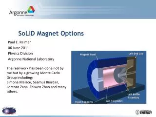
GSI 001: Dipole Parameters • RHIC dipole • Superconducting wire: • NbTi-Cu (1:2.25) • filament diameter 6 mm • twist pitch 13 mm • no coating • Rutherford cable • no core • Coil • phenolic spacer • Cu wedges • Yoke • Hc= 145 A/m • 6.35 mm laminations • RHIC type dipole GSI 001 • Superconducting wire: • NbTi-Cu (1:2.25) • filament diameter 6 mm • twist pitch 4 mm • Stabrite coating • Rutherford cable • 2 x 25µm stain- • less steel core • open insulation • Coil • stainless steel collar (G11 keys) • G11 wedges • Yoke • Hc= 33 A/m, 3.5% Silicon • 0.5 mm laminations, glued
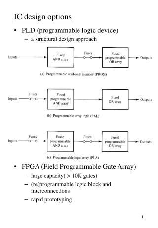
1T/s 2T/s 3T/s 4T/s 1T 6,9W ± 3W 15,3W ± 3W 28,6W ± 3W 44,3W ± 3W (43%) (19%) (10%) (7%) 27W by heater* 41W by heater* 13,8 J/cycle 15,3 J/Cycle 19 J/Cycle 22,2 J/Cycle 2T 7,6W ± 3W 16,3W ± 3W 30,8W ± 3W 52,1W ± 3W (40%) (18%) (10%) (6%) 38W by heater* 57W by heater* 30,4 J/cycle 32,6 J/Cycle 41 J/Cycle 52,1 J/Cycle 3T 7,6W ± 3W 15,9W ± 3W 30,1W ± 3W 53,2W ± 3W (39%) (19%) (10%) (6%) 28W by heater* 56W by heater* 45,6 J/cycle 47,7 J/Cycle 60,2 J/Cycle 79,8 J/Cycle 4T 7,1W ± 3W 17,0W ± 3W 34,0W ± 3W quench (42%) (17%) (9%) 40W by heater* 56,8 J/cycle 68 J/Cycle 90,7 J/Cycle *by heater; means an inexact additional measurement using the he ater power measurement in the distribution box ( ± 10W) Calorimetric Loss Measurements (C.Schröder) -
SIS 300 6 T Dipole • Central field: 6 T • Ramp rate: 1 T/s • Length: 1 m • Inner coil diameter: 100 mm • Two layers: inner: 4 blocks/outer: 3 blocks • Cooling: supercritical helium • Interlayer cooling channel • No holes in Kapton • Optimized end parts • Appropriate Ra of about 300 µ • Available in May 2008
Conductor for SIS 300 Same outer dimensions and number of strands as the cable for the outer layer of the LHC dipole
Wire and Cable R&D • Quench energy measurements for • different Ra in liquid helium (CERN) • Development of wires with CuMn • interfilamentary matrix • (INTAS/INFN) • Optimization of heat treatment to • adjust Ra (BNL) • Time dependent magnetization • measurements (Twente)
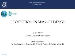
SIS300 Lattice Redefinition FBTR SIS 300 Lattice Doublet Lattice based on short straight dipoles New SIS 300 Lattice FODO Lattice based on long (and short) curved dipoles Small ring circumference and matching to SIS100 geometry requires FODO lattice in SIS300 and curved dipole magnets. Advantages a) chromaticity correction without significant DA reduction b) slow extraction with reasonable s.c. septum strength (P.Spiller, Fair Monthly, June 2007)