Download
1 / 24
240 likes | 304 Vues
Explore two crucial failures in high-temperature, high-pressure boiler components leading to equipment loss and injuries to plant personnel. Gain insight into the root cause analysis and structural damages, including grain boundary graphitization. Discover the inspection and testing methods used to identify failure mechanisms and prevent future incidents.

E N D
Material Tour of Boiler - Catastrophic Failures of Boiler Components Presented by George W Galanes, P.E. Metallurgical Consulting Engineer Diamond Technical Services, Inc
Introduction • Discuss two rather important and recent failures of high temperature and high pressure boiler components • Both failures were catastrophic and resulted in loss of equipment • One failure caused injury to plant personnel • What happened?
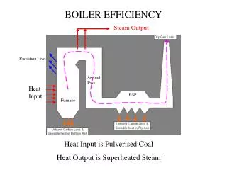
Typical Boiler Layout Pri SH Inlet Feeder Pipes (30 total) (136 sweeps) 6.625 “ O.D. x 0.935 “ minimum wall thickness of SA335 P1 material (carbon – moly steel). Design pressure is 4,180 psig and 830 deg. F.
History Repeats….. • ▪ 1982: - 5” long tight through wall crack found during hydro during forced outage - Boat sample analyzed by internal lab: “contained many sulfide inclusions”, no Charpy testing completed, no graphitization, inconclusive failure mechanism. - Repaired: grind / re-weld. • ▪ 1990: - Through wall crack found during hydro during a forced outage. - No metallurgical analysis completed - Repaired: grind / re-weld. • ▪ 2004: - Through wall crack / on-line leak - No metallurgical analysis completed - Replaced elbow with upgraded P22 material during a scheduled 11 day outage. • ▪ 2009: - Multiple elbow failure event during unit shut-down. - Metallurgical Analysis performed however results did not detect grain boundary graphitization because of unfamiliarity with the damage mechanism. • ▪ 2011: - Single elbow failure of a previously repaired elbow during steady state conditions. - Detailed seq. of events on subsequent slides.
What happened on that day • Sequence Of Events: • Thursday 2/10/11, Primary Superheater inlet pipe ruptured @ 7:37 a.m. (during normal AM load increase (5 mw/min) at 606 mwg) • INJURIES • Two Plant employees and one contractor employee were air lifted to a burn center • All with 2nd degree burns; released following day. • Two Plant employees taken by ambulance to regional Medical Center • Both released same day. • One employee treated for dust inhalation (Released same day)
Teamwork • A root cause analysis (RCA) team was assembled. • Team members consisted of operations personnel, plant personnel, and outside consultants to ensure a methodical review of events and known process for establishing causal factors. • In addition, fracture mechanics and boiler flow modeling were used to assist in RCA. • Outside entity was the lead in conducting the RCA to ensure independent technical oversight. • The failed sweep was sent to a metallurgical laboratory for comprehensive metallurgical analysis; • Chemical Analysis • Tensile testing • Hardness Testing • Impact testing • Metallographic examination
Look Closely It was determined that the cause of failure in the primary superheater (PSH) inlet sweep was a damage mechanism confirmed to be grain boundary graphitization.
What Happened…. • This type of damage mechanism is time dependent, meaning as the Grade P1 remained in elevated temperature service, the pipe would exhibit continued significant loss in toughness and ultimately fail catastrophically (no leak before break) in service. • The failure initiated and propagated from the OD surface of the bend extrados. This location would have been exposed to the highest forming strains. Bulk hardness testing confirmed the extrados as having the highest hardness( approximately 200 HV in comparison to straight sections at 165 HV). • Loss of toughness and significantly reduced elongation values were confirmed in the formed sweeps versus straight sections of Grade P1 piping based on extensive mechanical property testing.
Summary • Grain boundary graphitization was confined to formed bends did not appear to have been thermally treated after forming. • Because the grain boundary graphitization damage mechanism is not well understood or reported in literature it was more difficult to quantify severity of damage in comparison to the more traditional form of graphitization damage (graphite nodules). • Fortunately, after extensive sampling of sweeps and straight pipe sections of known Grade P1 PSH pipe material, there was no grain boundary graphitization observed in straight sections of Grade P1 pipe because these pipe spools contained no residual forming strains.
Based on the findings from the Unit PSH sweeps, a review was was performed to determine the extent of Grade P1 pipe material installed in this boiler and in a second boiler (sister unit). Carbon steel piping was also sampled as a precaution. No grain boundary graphitization damage was detected for carbon steel piping. In addition, a search of Grade P1 material was expanded to include the remaining coal-fired units for this client. No other Grade P1 piping was installed in the boiler proper. After careful review of metallurgical test results for sampled Grade P1 pipe material locations in both boilers, it was recommended to replace the original Grade P1 sweeps with SA 335 Grade P22 material and monitor the remaining P1 piping until full replacement using SA 335 Grade P22. Prevention…………..
Warm-Up Line Failure Investigation • Activities Associated with Root Cause Analysis and metallurgical failure analysis; • Mapping of the failed warm-up line • Removal and preservation of failed segments • Engineering Review of operating information • Engineering Review of the design basis of the warm-up line • Selection of a metallurgical lab to perform laboratory analysis in support of the failure investigation.
Results • Failure of the warm-up line internal wastage that weakened the pipe resulting in catastrophic rupture in service at multiple locations within the line. • The internal wastage corrosion from either stagnant or pooled condensate during off-line conditions from exposure to air atmosphere. There was no evidence of internal erosion or erosion/corrosion that contributed to the failure.
RCA Causal Factors • Reverted control logic for the 12” Fischer regulating valve that exposed the weakened line to internal operating pressure near main steam pressure conditions. • However, it is important to note that if the warm-up line did not sustain internal corrosion it would have safely accommodated main steam internal pressure based on original design (ASME B31.3). • Lack of urgency in reviewing the previous pipe inspection results from February, 2011. The pipe inspection results indicated excessive local wall thinning that if given proper review would have resulted in immediate corrective actions – repair or replace of severely thinned pipe sections prior to return to service. • The need to have a sufficient number of drains to ensure proper drainage of this warm-up line to prevent stagnant or pooling of condensate when the line is valved out.
Prevention Corrective Actions • Develop inspection plans for the warm-up line and other high energy steam lines. The inspection program results should be reviewed independently of site personnel to ensure no gaps or missed opportunities for corrective actions. • Survey the replacement warm-up line and other lines that are used on an infrequent basis to determine the need for drains or drain pots to avoid having similar internal corrosion problems.