Download
1 / 27
340 likes | 917 Vues
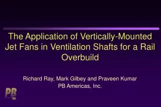
The Application of Vertically-Mounted Jet Fans in Ventilation Shafts for a Rail Overbuild. Richard Ray, Mark Gilbey and Praveen Kumar PB Americas, Inc. Railroad Tunnel Ventilation Requirements. Normal Operations: Removal of Heat Dilution of Combustion Products from Diesel Locomotives

E N D
The Application of Vertically-Mounted Jet Fans in Ventilation Shafts for a Rail Overbuild Richard Ray, Mark Gilbey and Praveen Kumar PB Americas, Inc.
Railroad Tunnel Ventilation Requirements • Normal Operations: • Removal of Heat • Dilution of Combustion Products from Diesel Locomotives • Train Fire Emergency: • Provide Tenable Evacuation Path for Evacuating Passengers per NFPA 130
“Piston Effect” Longitudinal Ventilation (Normal) Ventilation Shafts Portal Portal Direction of Train Travel
Supply Fans Exhaust Fans Direction of Passenger Egress “Push-Pull” Longitudinal Ventilation (Emergency)
Isometric View of Overbuild Building “A” Building“I” NorthPortal Length = 914.4 m (3,000 ft) Width = 9.75 to 15.24 m (32 to 50 ft) Height = 5.56 to 8.53 m (18.25 to 28 ft Building“O” South Portal
Overbuild Natural/Mechanical Ventilation: Buildings “A” – “E” Damper Damper Shaft Fan Shaft Fan Extraction Duct Fans Portal Stopped Train Portal
Overbuild Ventilation System Buildings “F” – “O” • Jet Fans Vertically-Mounted on Shaft Walls Near Base of Shaft • Dampers at Top of Shaft Eliminated • Jet Fans Run for Fire Emergencies and High NO2
Jet Fan Performance • Momentum Exchange Between Faster Moving Jet of Air Discharged from Fan and Surrounding Airstream • Only a Portion of the Total Flow Passes through Jet Fan • Remainder Passes Around Fan and is Accelerated by the Jet • Work Best with Low Resistance, Low Velocity Tunnel or Shaft
Saccardo Nozzle High Velocity Nozzle Induced Airflow Through Tunnel
Design Considerations:Building “I” Jet Fans • Target Airflow Total of 236 m3/s (500,000 cfm) for the Two Shafts • Determine Required Jet Fan Thrust • Calculate Shaft and Plenum System Resistance and Resulting Pressure Drop • Offset by Pressure Rise Due to Shaft Stack Effect (Estimated Smoke Temperature = 107°C [225°F])
Preliminary Building “I” Shaft and Plenum Geometry • Shaft Areas: 4.5 m (14.8 ft) by 3.05 m (10 ft) • Shaft Heights: 24.8 m (81.2 ft ) • Single Approach to Shaft from Plenum w/Turning Vanes at Bottom of Shafts • Series of 1.5 m (5.0 ft) by 1.5 m (5.0 ft ) Openings in Top of Crash Wall to Plenum • Plenum Height 1.6 m (5.1 ft) to 2.1 m (6.9 ft)
Plan View of Building “I” North Shaft and Plenum Calculated Overall Pressure Drop = 0.184 kPa (0.738 in. w.g.)
Stack Effect DPstack = Dr g h=0.062 kPa (0.25 in. w.g.) Where: DP= Stack effect pressure rise (kPa [in. w.g.]) Dr= Difference between ambient temperature and the average smoke temperature air density (kg/m3 [lb/ft3]) g = Acceleration due to gravity (m/s2 [ft/s2]) h = Vertical height of shaft (m [ft])
Jet Fan Thrust Where,Thrust in N (lb) is calculated from: b= Jet fan effectiveness Ashaft= Shaft cross sectional area (m2 [ft2]) rsmoke= Smoke density (kg/m3 [lb/ft3]) rstd= Air density at which fan was rated (kg/m3 [lb/ft3])
Jet Fan Effectiveness (b ) • Ability of Fan to Transfer Momentum to Surrounding Airstream • b = 1.0 for Fans Located in Center of Shaft and Away from Shaft Walls • For Fans Close to Corners, Walls and Other Fans, bCould Be as Low as 0.77
Correction Coefficient for Shaft Velocity • Tunnel Air Velocity “Offloads the Fan Compared to Still Air Conditions” (Woods) • Jet Fan Velocity of 36.3 m/s (7,140 fpm); Shaft Velocity of 11.6 m/s (2,280 fpm) • Coefficient of 0.68 x b of0.77 = Overall Correction of 0.52
Jet Fan Selection • Overall Coefficient of 0.65 Used • Total Thrust Required per Shaft = 3,514 N (790 lb) • Three 0.9-m (2.96-ft) Dia. Jet Fans per Shaft Assumed for Initial CFD Runs • Thrust = 3,079 N (687 lb) to Match Fans in Other Shafts
Results of Initial CFD Analysis • Total Airflow for Two Shafts of 310.4 m3/s (668,000 cfm) • Smoke Layers Still Unacceptably Low in Some Segments of the Evacuation Path • Shafts Increased to 5.84 m (19.2 ft) by 3.05 m (10 ft) for Next Iteration • 4th Jet Fan Added – Total Thrust of 4,095 N (916 lb) Per Shaft
Revised Building “I” Shaft and Plenum Configuration South Shaft North Shaft Plenum Crash Walls
Revised Fan/Shaft Performance Air Velocity (fpm) South Shaft 184.53 m3/s (391,000 cfm) North Shaft 164.24 m3/s (348,000 cfm)
Section View of Air Velocity Vectors Through Shafts Air Velocity (fpm) Air Velocity (fpm)
Air Velocity Contours at Fan Discharge and Top of Shafts Air Velocity (fpm) North Shaft South Shaft
Calculations vs. CFD Analysis • Stack Effect Less than Calculated Due to Dilution from Make-Up Air • Calculations Repeated Using CFD Output • Shaft Smoke Temperature of 58°C (136°F) • Make-up Air Pressure Drop of 0.027 kPa (0.110 in. w.g.) • Overall Correction Coefficient of 0.625 Calculated • With ShaftCoefficient from Table of0.71,yields b of 0.88 instead of 0.77
Conclusions • Jet Fans Can Be Used to Induce High Airflow Quantities Through Shafts in Tunnel Ventilation Systems • Jet Fan Thrust Estimates Should Account for Efficiency (b) and Shaft Velocity Correction Factor • Jet Fan Efficiency (b) Not as Adversely Impacted by Shaft Length and Proximity to Walls/Corners as Predicted