Power-bus Block Implementation
180 likes | 272 Vues
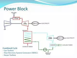
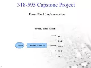
Power-bus Block Implementation. Power1 at the bus. RF. 1. U I.1. 12V DC Battery. CPU. 1. SC .1. Power-bus Block Introduction Description Power at the Bus ( 12 V DC battery supply to) • UI.1 5V and 500mA • RF.1 3.3V and 60mA

Power-bus Block Implementation
E N D
Presentation Transcript
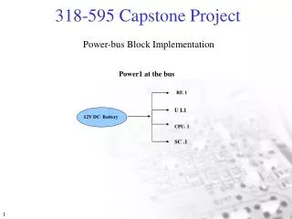
Power-bus Block Implementation Power1 at the bus RF. 1 U I.1 12V DC Battery CPU. 1 SC .1
Power-bus Block Introduction Description Power at the Bus ( 12 V DC battery supply to) • UI.1 5V and 500mA • RF.1 3.3V and 60mA • CPU.1 3.3 V and 25mA • SC.1 5V and 30mA
Power1 at the bus +3.3V 60mA TRANSC.1 +5V 500mA U I.1 Power1 Block Diagram 12 V DC Battery PS1 +3.3V 25mA CPU1 +5V 30mA SC.1
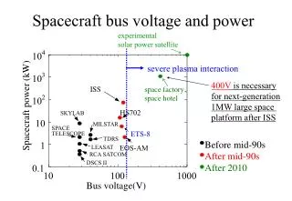
Power Block Performance Requirements Power Inputs: • 12V DC input (Bus Unit) ranging from 57 - 63 Hz Electrical Functions: • Power supply to the CPU, Set up Control, UI and Transceiver Electrical Interfaces: • Analog, Digital and Power Signals • Bi-Directional RF Transceivers • RS232 Network Interface
Power-bus Block Performance Requirements Electrical Functions: • Power Modes: • On, Off • Function Modes: • Normal • Configure • Functional Features: • Bus Call • Taxi Request Electrical Interfaces: • Analog, Digital and Power Signals • Bi-Directional RF Transceivers • RS232 Network Interface
Power-bus Block Standard Requirements Energy Source: • 12 V DC ( 10.2V to 13.8 V DC +-15% ) • 60 Hz ( 57 to 63 Hz +-5% )
Power_bus Block Standard Requirements Modes: • On ( Primary, 120 VAC) Frequency Range: • 60 Hertz ( 57 to 63 Hz range) Safety current: • 1.5 A max current limit protection • 12 V maximum potential of user surface
Standard System Level Requirements • Standard Requirements • Environmental: • Operating Temperature Range: -40 to 70 °C • Operating Humidity Range: 2 to 98 % • Storage Temperature Range: -30 to 80 °C • Storage Humidity Range: 2 to 98 % • Storage Duration: 2 Years • Energy Sources: • 12 VDC (10-15 V) • Over Voltage Protection Circuitry
Power Block Standard Requirements Mechanical: • Maximum area of the power supply board is 200 cm² Life Cycle: • Production Life 5 Years • Full Warranty Period: 1 Year • Service Strategy: Distributor Repair
Power Block DFM Plan • Product Code 265089 • Price $15 • 12V / 1.2A Sealed Lead Acid Battery • Chemistry SLA • mah: 1.2 • Volt: 12 • Color: Black • Weight: 1.125 lbs