Download
1 / 24
240 likes | 246 Vues
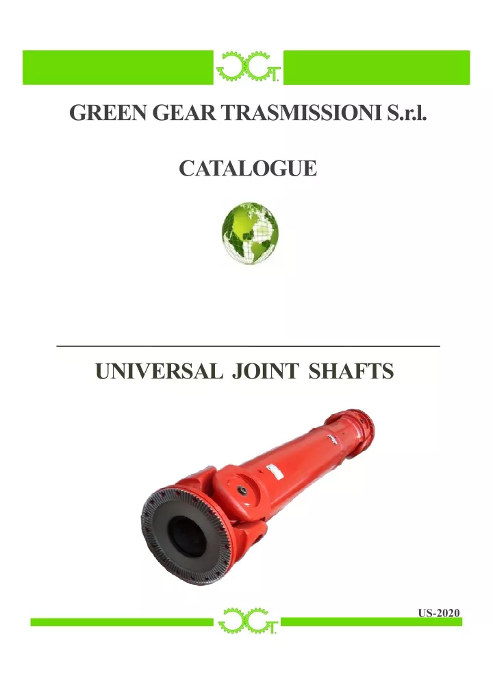
Universal joint shafts transmit torque from a driving machine to a driven machine and can accommodate a high degree of misalignment. The universal shafts are selected according to their load features, calculated torques, bearing lifetime, rotation speed and working angle. Our Universal Shafts catalogue relates to production of Universal Shafts, and provides a description of their technical specification in order for a proper measurement. For more info, visit our website Green Gear Trasmissioni Srl today.

E N D
GREEN GEAR TRASMISSIONI S.r.l. CATALOGUE UNIVERSAL JOINT SHAFTS US-2020
Copyright 2021 GREEN GEAR TRASMISSIONI S.r.l. Baldichieri D’Asti– Italia EDIZIONE US-2020
TABLE OF CONTENTS COMPANYINTRODUCTION………………………………………………..….…….…...…...pag.1 UNIVERSAL SHAFT FEATURES…………...……………………………….……….……......pag.2 WORKSHOP………………………………………………………………….………………….pag.3 SELECTION & DIMENSIONING…………………………………………..…………………..pag.4 US.A LIGHT DUTY SERIES………………………………………………..…….………...…..pag.5 US.A ENGINEERING DATA……………….………………………………..………….....……pag.6 US.B MEDIUM DUTY SERIES (TYPESA-B-C-D-E)………………………..….………...…..pag.7 US.B ENGINEERING DATA……………….…….……………………………..………......…..pag.8 US.C HEAVY DUTY SERIES…………………………………………………..….…….…...…pag.9 US.C ENGINEERING DATA……………….…….…………………………….……….....…..pag.10 US.F TUNNEL SHAFT SERIES………………………………………………….………...….pag.11 US.F ENGINEERING DATA……………….…….……………………………………........…pag.12 COMPANION FLANGE………..……………………………………………………………....pag.13 COMPANION FLANGE BORES…..…………………………………….................................pag.14 INSTALLATION………………….……………………………………....................................pag.15 MAINTENANCE, LUBRICATION…..……………………………….....................................pag.16 ROLLING MILLAPPLICATION DATA…..……………………..……………………………pag.17 PICTURES……………………………………………………………………………………...pag.18 PICTURES……………………………………………………………………………………...pag.19 PICTURES……………………………………………………………………………………...pag.20
The Company The Company Green Gear Trasmissioni Srl was founded with the goal and purpose to work side by side with customers to study and develop with them the most adequate solution. Thanks to our skills and experience, gained in more than twenty years, the Company guarantees high quality production at very Specializing in the transmission equipment, the Company is able to offer the market the manufacturing solution on specific customer requirement. Although particular application experience and flexibility enables us to meet the needs of any industrial field, both in terms of application, and in terms of final product quality level. The production area and offices are located in Asti (Piedmont), geographically well located: very close to suppliers, available within a radius of 200 km, and to seaports and airports for international transport. competitive production prices. power of best technical and our rolling products find our in mills, 1
Production range 1. 2. 3. UNIVERSAL SHAFTS GEAR SPINDLES GEAR COUPLINGS The universal shaft enables motion transmission between driving and driven shafts, with wide working angles. The major characteristic of a universal shaft is having a transmission ratio instantly varying, when misalignment is different from zero. The transmission ratio average value however keeps uniform; to annul such variability, the connection is made by two universal joints, equalizing the angular velocity. Motion transmission is realized by a component connecting input and output shaft ends. This component is called journal cross. Generally speaking, the universal shaft operation can be distinguished into 5 single peculiarities: 1. Torque and speed 2. Possibility of changing the distance between input and output 3. Possibility of changing the angle between input and output 4. Stress for vibration 5. Torsional strength Great part of the energy produced under these extreme operation conditions is partially absorbed by the universal shaft, and partially by the connected components. Our universal shafts, along with a range of products covering any application of the market, offer excellent quality level, operational safety, long working life and low maintenance costs. Especially in iron and steel field, with hard and heavy duty applications, our universal shafts are the correct choice for the following manufacturing features: Monolithic yoke Higher misalignment and minimum torsion under high loads Better capacity of bearing high torque loads Perfect design and construction of every single component Selected and heat treated materials First-rate weldings Our universal shafts are custom-made, following the customer’s requirements. They are welded by skilled personnel, who then check weldings by ultrasonic instruments, and proceed with dynamic balancing following G16 grade and DIN ISO 1940 standards. On demand, higher grade balancing can be realized. Then, the universal shafts are lubrified according to the customer’s specifications and the application they are designed for, and they are finally painted. We are able to meet every requirement by guaranteeing the best service, thanks to our flexible manufacturing process, to our full stock availability, and to our skilled collaborators. 2
Workshop Green Gear Trasmissioni Srl is specialized in the production of universal shafts, thanks to its executives’ twenty-year wealth of experience, and ranks as a field specialist leader. Our universal shafts find their best application in the fields of steel rolling, rubber and plastic, paper, marine industry, lifting, shredding mills and drilling. Our customers are all over the world, mainly in Europe, Asia and America. We have solved application problems to many customers through manufacturing modifications and special innovative devices, currently being patented. Our target is maintaining our quality standards along with the highest technologic development, thanks to continuous research and daily studies with the best collaborators of the field, and customers’full satisfaction as the result of our serious involvement in finding the best solution. The efforts focused on design improvement and technological innovations enable us to offer high- quality and first-rate shafts. Our strengths are: • Bearing longer lifetime; • High precision in machining operations; • High quality of balancing; Our one of a kind sealing system assures an excellent lubrication and consequent bearing longer lifetime. The precision of splined shafts and sliding tubes is achieved by one-step broaching machines; performance universal tooth surfaces are nitrided, so to guarantee their lifetime. Our universal shafts are welded, checked by ultrasonic inspections and balanced within efficient manufacturing process. Quality Program The outstanding points of our quality program are: Operating under ISO 9001:2000 certification standards High-level managing system, with Pert and Gant diagram processing State of the art design and engineering instruments High-qualified personnel, devoted to the mutual goal of customers’complete satisfaction Most up-to-date instruments for manufacturing process check, along with production equipment accurately selected 3
Selection & Dimensioning To select US.A and US.B universal shaft series, please follow the following procedure. For remaining series, kindly contact us. (1), (2) and (3) where: Tc = Calculated torque [Nm] T = Nominal torque [Nm] Pw = Motor power [kW] PH = Motor power [kW] N = Rotation speed [rpm] K = Service factor 1. The universal shafts are selected according to their load features, calculated torques, bearing lifetime, rotation speed and working angle. 2. The calculated torque is given by the following formulas (1), (2) or (1), (3): 3. Generally, the universal shafts are selected following the torque to be transmitted and the expected bearing lifetime. 4. Check the torque following the formula (4): Tc ≤ Tn or Tc ≤ Tf or Tc ≤ Tp.......(4) (4) where: Tc = Calculated torque [Nm] Tn = Nominal torque [Nm] (theoretically calculated, according to the following conditions, for example: shaft speed n = 10 rpm, angle β = 3° and bearing lifetime LN = 5000 hours under load). Tf = Fatigue torque suitable for alternate loads [Nm] Tp = Pulsating torque suitable for pulsating loads [Nm] Tp = 1.45 Tf 5. Check the bearing lifetime following the formula (5): 6. In case the universal shaft has both horizontal and vertical misalignment, its composite misalignment is calculated by the formula (6): where β is the composite angle, β1 is the horizontal angular misalignment and β2 the vertical one. 7. If the flange diameter is 390 mm or smaller, the formulas (7) and (8) shall be used to check the rotation maximum speed: nmax ≤ nβ……………………………..(7) maximum permissible speed on working angle – Figure 7.1 nmax ≤ nL……………………………..(8) maximum permissible speed on operating length – Figure 7.2 8. If the universal shaft speed line is higher than 7 m/s, a test of dynamic balancing is required, normally with precision class between G6.3 e G16. Complex variables may influence the grade of balancing. 4
LIGHT DUTY UNIVERSAL SHAFT –US - A SERIES DESIGNS TYPE A TYPE B TYPE C 5
LIGHT DUTY UNIVERSAL SHAFT -US.ASERIES ENGINEERING DATA SIZE DATA US.A 58 US.A 65 US.A 75 US.A 90 US.A 100 US.A 120 L min. 225 165 285 165 335 200 285 182 226 366 445 226 296 261 366 242 500 211 294 237 261 242 286 376 Lv 35 15 40 15 40 30 45 30 25 100 55 25 50 5 100 15 80 25 50 5 5 15 15 70 Tn [Nm] 180 260 240 260 500 560 800 560 860 1800 1200 860 1100 1800 2700 2300 860 1100 1800 2700 3300 5200 Tf [Nm] 90 180 120 180 250 280 400 280 430 900 600 430 550 900 1350 1150 430 550 900 1350 1650 2600 β (°) 35 29 35 29 35 25 35 20 28 28 35 28 25 28 30 35 28 25 18 28 30 28 25 D 52 59 63 59 72 77 92 77 90 90 100 90 100 122 90 98 112 90 100 122 98 136 138 Df DIN58 DIN65 DIN75 DIN90 DIN100 DIN120 D1 47 52 62 74.5 84 101.5 D2 30H7 35H7 42H7 47H7 57H7 75H7 D3xδ min. 38X1.5 35X3 45X1.5 51X2.5 51X2.5 63.5X2.5 51X2.5 60X2.5 76X2.5 51X2.5 51X2.5 76.2X2.4 60X2.5 89X2.5 60X2.5 60X2.5 90X4 75X3 90X4 Lm 32 37 39 37 45 42 52 33 50,5 55 50,5 53 68 51 54 63 43 53 56 68 54 72 73 (TYPE C) L 128 148 156 148 180 168 208 132 202 220 202 212 272 202 216 252 172 212 224 272 216 288 292 K 3.5 4 4.5 4 5.5 6 6.5 7 8 7 8 7 8 8.5 8 t 1.5 2 1.7 2.8 2 2.5 2.8 2.5 2.6 2.5 2.7 2.5 3 2.6 3.1 2.8 n 4 4 6 4 6 4 6 8 d 5 6.5 6 6 8 6 8.5 8 8.5 8 10.5 10 SIZE DATA US.A 150 US.A 180 US.A 200 US.A 225 US.A 250 L min. 590 286 484 376 567 599 544 640 612 600 640 580 753 761 618 605 690 775 860 753 597 690 690 Lv 80 15 110 70 120 100 110 80 100 120 110 140 110 100 120 140 110 110 110 Tn [Nm] 4500 3300 5000 5200 6200 10000 10500 8400 10000 12000 13000 16000 19000 27000 16000 22000 16000 19000 27000 27000 Tf [Nm] 2250 1650 2500 2600 3100 5000 5250 4200 5000 6000 6500 8000 9500 13500 8000 11000 8000 9500 13500 13500 β (°) 35 28 30 25 35 25 25 35 30 25 25 30 25 30 25 25 18 28 30 28 25 D 142 136 125 138 141 158 160 154 158 170 172 178 204 187 122 98 136 204 Df DIN150 DIN180 DIN200 DIN225 DIN250 D1 130 155.5 170 196 218 D2 90H7 110H7 125H7 140H7 140H7 D3xδ min. 102X3 90X4 76.2X2.4 90X4 85X5 100X6 120X4 120X3 100X6 120X4 112X7 120X6 140X5 112X10 140X6.5 112X7 120X6 140X5 140X5 Lm 85 72 78 73 86 89,5 90 87 96 90 100 95 96 100 96 100 110 110 120 96 96 110 110 (TYPE C) L 340 288 312 292 344 358 360 348 384 360 400 380 384 400 384 400 440 440 480 384 384 440 440 K 10 12 14 14 15 15 15 15 18 t 3 3.3 3.1 3 3.3 4 3.3 3 3.4 2.9 4 5 5 5 5 6 n 8 8 8 10 8 8 10 8 10 8 8 8 12 8 12 8 8 d 13 12 15 14 16 14 16 17 17 16 16 16 18 NOTES: 1) 2) Millimeters are used as measurement units except where indicated. L = standard length, shorter or longer lengths are available on demand. Lv = standard length compensationwhere present. m = weight, referred to the dimensions of the catalogue. mL = weight each 100 mm of tube. Tn = nominal torque Tf = fatigue torque, i.e. the permissible torque calculated on the fatigue strength under reversible loads. 3) Please contact us for special dimensions. 6
MEDIUM DUTY UNIVERSAL SHAFT -US.BSERIES DESIGNS A B C D E 7
MEDIUM DUTY UNIVERSAL SHAFT -US.BSERIES DESIGNS & ENGINEERING DATA SIZE DATA 160 L 740 Lv m (kg.) L 480 m (kg.) L 380 m (kg.) L 520 m (kg.) L 800 Lv m (kg.) β (°) D 160 Df 160 D1 137 D2 (H7) D3xδ 114x10 Lm K t n d b g US.B US.B 180 US.B 200 US.B 225 US.B 250 US.B 265 US.B 285 US.B 315 US.B 350 US.B 390 US.B 440 US.B 490 US.B 550 US.B 620 TYPE 800 900 120 1000 1060 1120 140 1270 1390 1520 150 1530 170 1690 1850 2060 240 2280 250 A 100 190 65 83 115 152 219 260 311 432 610 804 1122 1468 2154 2830 530 590 640 730 790 840 930 1000 1010 1130 1240 $1400 1520 B C D 44 60 85 110 160 180 226 320 440 590 820 1090 1560 2100 420 440 500 560 600 640 720 780 860 1040 1080 1220 1360 35 48 66 90 130 160 189 270 355 510 780 970 1330 1865 580 620 690 760 810 860 970 1030 1120 1230 1360 1550 1720 48 65 90 120 173 220 250 355 485 665 920 1240 1765 2390 850 940 120 1050 1120 1180 140 1320 1440 1550 150 1710 170 1880 2050 2310 240 2540 250 E 100 190 70 92 126 168 238 280 340 472 660 886 1230 1625 2368 3135 15 180 200 225 250 265 285 315 350 390 440 490 550 620 180 225 200 225 225 250 250 285 265 285 315 315 350 350 390 390 440 440 490 490 550 620 155 196 170 196 196 218 218 245 233 245 280 280 310 310 345 345 385 385 425 425 492 555 90 90 105 90 105 105 105 105 125 125 125 130 130 155 155 170 170 190 190 205 205 250 280 127x10.5 146x11.5 159x10.5 180x12.5 194x13.5 203x14.5 219x16.5 245x19 273x21 325x25 351x30 402x32 426x40 95 105 110 125 140 150 160 180 195 215 260 290 305 340 16 17 20 18 20 20 25 25 27 25 27 32 32 35 35 40 40 42 42 47 47 50 55 4 5 5 5 5 5 6 6 7 5 7 8 8 8 8 8 8 8 10 12 12 12 12 8 8 8 8 8 8 8 8 8 8 8 10 10 10 10 10 16 16 16 16 16 16 16 15 17 17 17 17 17 17 19 21 19 21 23 23 23 23 25 25 28 28 31 31 31 38 20 24 32 28 32 32 40 40 40 40 40 40 40 50 50 70 70 80 80 90 90 100 100 6.0 7.0 9.0 8.0 9.0 9.0 12.5 12.5 15.0 12.5 15.0 15.0 15.0 16.0 16.0 18.0 18.0 20.0 20.0 22.5 22.5 22.5 25 Tn (kNm) 21 28 40 56 80 100 120 160 225 320 500 700 1000 1250 TORQUES Tf (kNm) 10.5 14 20 28 40 50 58 80 110 160 250 350 500 625 Tp (kNm) 15.2 20.3 29 40.6 58 72.5 87 116 159.6 232 362.5 507.5 725 906.2 Tcs (kNm) 28 36 52 73 104 130 156 208 292.5 416 650 910 1300 1625 NOTES: L = standard length, shorter or longer lengths are available on demand. Lv = standard length compensation, where present. m = weight, referred to the dimensions of the catalogue. Tn = nominal torque Tf = fatigue torque, i.e. the permissible torque calculated on the fatigue strength under reversible loads Tp = Pulsating torque Tcs = Limit torque Please contact us for special dimensions. 8
HEAVY DUTY UNIVERSAL SHAFT -US.CSERIES DESIGNS 9
HEAVY DUTY UNIVERSAL SHAFT -US.CSERIES ENGINEERING DATA US.C 680 US.C 700 US.C 750 US.C 780 US.C 800 US.C 840 US.C 900 US.C 920 US.C 1000 US.C 1060 US.C 1100 US.C 1200 SIZE DATA TYPE L 1540 1600 1840 1920 2120 2280 2380 2480 2500 2720 C D m (kg.) 3150 3450 4300 4680 5050 6400 8420 8950 10600 12100 13500 16900 L 1940 2100 2400 2500 2680 2950 3130 3200 3300 3570 m (kg.) 3220 3530 4500 2400 5800 7470 9980 10500 12300 14500 15800 19500 L 3230 3460 3620 4000 4250 4580 4770 4950 5100 5660 E Lv 250 300 m (kg.) 4880 5400 8000 8450 9070 11800 15900 16500 19900 22000 27500 34800 β (°) 15 D 680 700 750 780 800 840 900 920 1000 1060 1100 1200 Df 680 700 750 780 800 840 900 920 1000 1060 1100 1200 D1 635 695 725 745 775 835 855 915 980 1015 1100 D2 (H9) 550 570 610 640 660 710 740 760 840 920 1000 D3 560 620 660 750 790 800 850 900 Lm 385 400 460 480 530 570 595 620 625 680 K 70 95 110 120 130 n 24 20 d 26 31 36 38 50 45 50 58 TORQUES Tn (kNm) 1640 1750 2250 2500 2670 3100 3800 4050 5200 6500 6900 9000 Tf (kNm) 980 1050 1350 1500 1600 1860 2280 2430 3120 3900 4140 5400 NOTES: 1) 2) Millimeters are used as measurement units except where indicated. L = standard length, shorter or longer lengths are available on demand. Lv = standard length compensationwhere present. m = weight, referred to the dimensions of the catalogue. mL = weight each 100 mm of tube. Tn = nominal torque Tf = fatigue torque, i.e. the permissible torque calculated on the fatigue strength under reversible loads. 3) Please contact us for special dimensions. 10
TUNNEL UNIVERSAL SHAFT -US.FSERIES DESIGNS 11
TUNNEL UNIVERSAL SHAFT -US.FSERIES ENGINEERING DATA SIZE TYPE US.F 225/315 US.F 250/330 US.F 285/390 US.F 315/435 US.F 350/490 US.F 390/550 US.F 435/600 US.F 480/640 DATA Lmin 920 1020 1140 1300 1445 1605 1760 1955 EA Lv 650 700 750 800 900 Lmin Lv Lmin 260 650 610 285 700 655 325 360 400 445 500 570 EB 750 800 900 750 827 885 985 1124 1225 EC Lv 650 700 750 800 900 Lmin 740 820 925 1050 1140 1250 1385 1535 ED Lv 650 700 750 800 900 β (°) 15 / 5 Dfx D1x D2x bx tx gx Kx Lm(x) Dfy Ly D1y D2y by ty gy Ky Lm(y) n1 - d1 n2 - d2 S D3 V Ry 225 196 105 32 250 218 115 285 245 135 40 315 280 150 350 310 165 50 390 345 185 70 435 385 200 80 10 20 42 260 600 390 550 420 80 12 20 480 425 225 90 12 22.5 47 290 650 410 595 450 90 15 22.5 5 7 8 9 12.5 25 140 330 200 315 240 15 16 35 195 480 290 435 335 50 18 40 215 520 320 480 385 70 20 125 315 190 285 220 32 5 9 28 140 27 160 390 230 355 270 40 32 180 435 250 390 300 7 8 10 12.5 30 150 15 16 47 210 18 50 230 40 170 42 190 60 280 290 10 - ϕ23 10 - ϕ23 8 - ϕ17 8 - ϕ19 8 - ϕ21 10 - ϕ25 16 - ϕ28 16 - ϕ31 8 - ϕ17 102.18 146 395 315 215 8 - ϕ19 117.72 159 435 330 283 8 - ϕ21 127.7 180 480 390 400 10 - ϕ25 177.24 245 695 520 1013 16 - ϕ28 201.25 273 735 600 1410 16 - ϕ31 225.25 325 810 650 2040 137.5 203 565 435 533 165.2 219 630 480 721 Lmin kg. 100mm 6.4 8.5 10 11.6 16.8 19.4 25 31.3 TORQUES Tn (kNm) 56 80 120 160 225 320 500 700 Tf (kNm) 28 40 58 80 110 160 250 350 12
COMPANION FLANGES We can manufacture any type of companion flanges, following your requirements. Generally speaking, these sleeves are devided into 2 families, following their geometric shape: a. CYLINDRICAL COMPANION FLANGES b. FLANGED COMPANION FLANGES Or, following the type of connection between its flange and the universal shaft one, they are divided into 5 categories: 1. FLANGE WITH NO KEYWAY 2. FLANGE WITH KEYWAY 3. FLANGE WITH HIRTH SERRATION (as the picture on the right) 4. FLANGE WITH DOG TEETH 5. FLANGE WITH NO KEYWAY WITH PINS ACCORDING TO DIN 15452 STANDARDS MAX ALLOWED FINISHED BORE DIAMETER PER SIZE US.B 160 US.B 180 US.B 200 US.B 225 US.B 250 US.B 265 US.B 285 US.B 315 US.B 350 US.B 390 US.B 440 US.B 490 US.B 550 US.B 620 SIZE DIAMETER [mm] 80 90 100 115 125 130 140 165 185 205 225 255 295 330 13
COMPANION FLANGE - FINISHED BORE TYPOLOGIES 1. CYLINDRICAL FINISHED BORE & 1 KEYWAY 2. CYLINDRICAL FINISHED BORE & 2 KEYWAYS @ 90° 3. CYLINDRICAL FINISHED BORE & 2 KEYWAYS @ 120° 4. CYLINDRICAL FINISHED BORE & 2 KEYWAYS @ 180° 5.TAPER FINISHED BORE & 1 KEYWAY 6. TAPER FINISHED BORE & 2 KEYWAYS @ 180° 7. CYLINDRICAL FINISHED BORE WITH SHRINK FITTING & OIL PRESSURE REMOVAL 8. FINISHED BORE WITH FLAT WEAR KEYS 14
INSTALLATION, MAINTENANCE & LUBRICATION BEARINGS The composition of the journal cross bearings is shown in Figure 1.1. Three lines of rolls (7) are axially placed inside the bearing ring (6), closed by a ring (2), a seal (3), a flat spring, and held by a seal ring (4). A composite thrustbearing disc is placed at the bearing bottom with a grease nipple outside the bearing centre (10). The bearing is held inside the yoke by a seal ring (9). Figure 1.1 PRELIMINARY INSTRUCTIONS If the universal shaft needs to be kept in stock for long before installation, do not remove the protection applied on the most exposed critical surfaces. If stocked outdoor, the universal shaft must be placed on supports keeping it separated from the ground, and must be protected from rain and other atmospheric events. When moving it, insert wooden chocks in the open surfaces of the yokes, to avoid any angle misalignment and to handle safely. When transporting or lifting universal shafts, Figure 2.1 do not rope belts or chains on the tube surrounding the spline, or on the protection tube in case of telescopic universal shafts. In fact, the universal shaft may fully open, get damaged, and endanger things and people. Always handle and transport in horizontal position, except for universal shafts designed for specific vertical applications. See Figure 2.1 for the suitable way of lifting and handling. INSTALLATION The universal shaft installation shall follow its drawing specification. Drawing specifications are elaborated following the working conditions required by the customers. If properly installed, the universal shaft shall rotate with the motor shaft simultaneously, and the full rotating system will not swing. To this purpose, the manufacturer has adopted the following technological and engineering precautions: Flange yoke and bearing hole axis are on the same plane; The intermediate section yoke bearing holes and the intermediate shaft axis are on the same plane (See Figure 3.1); The journal cross axis are placed vertically and symmetrically on the same plane; During installation, make sure the two yokes and the intermediate shaft are placed in «W» and «Z» position and that their angles β1 and β2 are equal (see Figure 3.3 and 3.2). This way, any fitting side speed variation is annulled by the joint side speed variation, with consequent simultaneous rotation of the whole transmission. The following procedure is recommended for the universal shaft installation, after the alignment on the machines to be connected is done. Figure 3.1 Figure 3.2 - β1 = β2 Figure 3.3 «Z» installation «W» installation 15
INSTALLATION, MAINTENANCE & LUBRICATION COMPANION FLANGE INSTALLATION The different types of companion flanges require different assembly procedures. Please find below the installation procedures of two different types of companion flanges: 1. With taper bore (interference fitting): i. Please follow the drawing, and check: the companion flange bore diameter, the keyway and the key seat dimensions, the flange surface, the bore diameter and their distribution, and their connection interfaces, to check if they are corresponding (keyway, hirth serration, dog teeth) for proper fitting and assembly operations. ii. Remove any dirt from sleeve, centering and connecting shaft, and clean every fitting surface. iii. Fit the keyway into its seat and align wih the connecting shaft. iv. Uniformly heat at a temperature of 200°C, in a furnace or in oil bath to expand the hole. When heating the oil, be careful it doesn’t catch fire. You may also employ a heating torch, to heat the companion flange. While heating, continuously rotate the companion flange or turn the heating torch around it. The surface temperature shall be constantly checked and must not exceed 260° C, so to avoid overheating. v. Align the heated companion flange with the universal shaft keyway and fit it onto the shaft to be connected. If the universal shaft has no shoulder, prepare a lock to prevent the companion flange from sliding beyond the fitting limit. Let the companion flange cool down, before proceeding with any further operation and/or installation. 2. Fitting with no interference: i. Please refer to the drawing, and check: the companion flange bore diameter, the keyway and the key seat dimensions, the flange surface, the bore diameters and their distribution, and their connection interfaces, to check if they are corresponding (keyway, hirth serration, dog teeth) for proper fitting and assembly operations. ii. Remove any dirt from sleeve, centering and connecting shaft, and clean every fitting surface. iii. Position and fit the companion flange. iv. Check the roll fitting support devices are the proper ones. If any sleeve blocking or release device is present, please check their correct operation. UNIVERSAL SHAFT INSTALLATION Check that the yoke bearing holes in the intermediate section and the intermediate shaft axis are on the same plane (see Figure 3.1). This is an essential check. Check that the flange dimensions, and the whole universal shaft in general, are according to the drawing. Check that the different components are in good condition, and that the retainer rings are in their seats. Clean any dirt, if present. If the companion flange needs to be fitted onto a driving shaft, it has to be fitted onto the universal shaft first (see Figure 4.1). If the companion flange is already fitted onto the shaft, lift the universal shaft by a steel cable or by a chain for heavy loads, hanging it by its yokes, as shown in Figures 2.1 and 4.1. This allows the flanges to move, making the operations of alignment easier. Lift the universal shaft in the assembly position. Fit the companion flange onto the driving shaft first, when the companion flange has an interference hole. Align the keyways with their seats, insert the screws in the matching flange aligned holes and partially screw with their nuts, when the companion flange has a hole with no interference. Make the same operation for the driven side. After screwing all the bolts, tighten them by a dynamometrical wrench in a uniform and crosswise way. Check the tighthening torque of all the fitting devices. Remove any cable or chain employed. LUBRICATION The universal shafts, the telescopic ones in particular, need to be fully greased. Pump lithium # 2 based grease into the grease nipples placed on the journal crosses and on the intermediate section of the universal shaft (for telescopic universal shafts), until grease leaks out of the seals. Do not over-pressurize bearings while greasing. Figura 4.1 16
A pressure of 5 bar is strongly recommended. The telescopic universal shafts have to be greased in their fully compressed position, to avoid overfilling the splined shaft seat, which would compromise the length compensation operation. Warning: lithium based grease is not compatible with other types of grease. Always check its compatibility with the grease producer. LUBRICATION INTERVALS Grease all the bearings and the splined shaft, if present, before starting to work and after 500 working hours. Next greasings shall be made every 30 days. MAINTENANCE Our universal shafts require very low maintenance. However, if you follow a regular maintenance program, you will ensure the best performances and the longest lifetime. Daily check tightening on the fitting devices and on the flange meshings. If necessary, re-tighten them at the correct tightening torque. Regularly grease, as previously instructed. RollingMillApplication Data for Selectionand Design 17
Green Gear Trasmissioni S.r.l. Warehouse & Offices: Via NAZIONALE n.83 14011 BALDICHIERI D’ASTI (AT) – ITALIA Tel. +39 0141 203522 Tel. +39 0141 203010 Fax. +39 0141 1850491 Mobile: +39 338 2013358 info@greengeartrasmissioni.com www.ggtsrl.it EDIZIONE US-2020