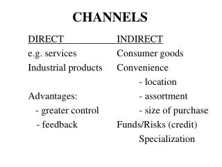
96 channels
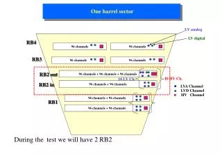
One barrel sector. LV analog. LV digital. RB4. 96 channels. 96 channels. RB3. 96 channels. 96 channels. RB2 out. 96 channels + 96 channels + 96 channels. 10 HV Ch. 10 LV Ch. RB2 in. 96 channels + 96 channels. LVA Channel. LVD Channel. HV Channel. 96 channels + 96 channels.

96 channels
E N D
Presentation Transcript
One barrel sector LV analog LV digital RB4 96 channels 96 channels RB3 96 channels 96 channels RB2 out 96 channels + 96 channels + 96 channels 10 HV Ch. 10 LV Ch. RB2 in 96 channels + 96 channels LVA Channel LVD Channel HV Channel 96 channels + 96 channels RB1 96 channels + 96 channels During the test we will have 2 RB2
RB2 Layout 1 RB2in case RPC Chamber FEB FEB FEB FEB FEB FEB FEC FEC FEC FEC FEC FEC FEC FEC FEC FEC FEC FEC 25 twisted pairs lines: 16 data lines plus 4 test input lines/FEB ALV1 DLV1 ALV2 DLV2 HV1 HV2
8 8 DAC Voltage Regul Voltage Regul RPC FE board & Service board architecture From strip From strip FEC FEC power & control flat cable (Power, I2C Lines) (20 pin) 2 2 LVDS-R LVDS output + Test Input from LB (50 pins)
LV Power supply FEB Kapton conn. DGND Cu Foil (signal ground) AGND Gaps Pet Foil Cu Foil HV connector HV Ground Al chassis HV Power supply
Chamber almost final layout Capton foil 2 electronics boards: 32 channels 1 board: 2 chips (8 strip/chip)
2001 Test_Beam Layout 384 strips LVDS Input Control room GIF AREA LVDS Input /RPC VME TDC HV cables SYS 1527 LV P.S. LV P.S. LVDS signals need short cables (max 15 m)
Control room CMS Control room Source Layout of GIF and surrounding Gas box Muon CMS Stokage box
Trigger and rate Small trigger SCI1 .and. SCI2. .and. SCI3.and.SCI1 Chamber position important for the rate of hits
Material • 2 RB2: 2 x 12 FEB 384 strips 6 TDCs (Bari) 1 VME crate • 3 Beam chambers 12 output NIM 1 TDCs • 8 HV channels 1 HV module 1 CAEN SYS 1527 Power Supply 2 LV Power Supply • 4 LV channels • Signal thresholds: set and reading PC controlled • 1 Temperature-Pressure controller
Le unità del Sistema di Acquisizione per RPC Implementazione software cpu vme RU Pacchetto XDAQ (Cross data Acquisition) è costituito da tre unità separate e autonome. TRIGGER EVM Run Control BU Scrittura su PC linux file Monitoring
TDC Per testare gli RPC il DAQ deve fornire ad ogni segnale di trigger informazioni relative alla presenza o meno di impulsi generati al passaggio di un muone sulle strisce di ciascun rivelatore. A tal scopo è stato realizzato il TDC (VME Common stop, risoluzione massima 25 ns). Il TDC acquisisce in modo continuo sia pattern di hit da rumore che da cosmici a partire dalla sua abilitazione fino al suo stop. BUS TRANCEIVER LVDS RECEIVER INPUT[63:0] LIFO 64 x 64 IN[63:0] 32 32 VME BUS OR OR8[7:0] INTERNAL BUS OR64 32 TRIGGER SHIFT REGISTER 64 IN[63:0] CONTROL LOGIC RATE COUNTER OR8[7:0] 32 MUX OR64 TIMER 32 MUXSEL
Evento = insieme di pattern di hit che per ogni segnale di trigger vengono memorizzate nei moduli di memoria (LIFO). LIFO 1 word 2 word 1 0 0 2 Bit_L=0x18000000 0 0 I 3 0 1 N 4 1 1 G 1word 1 0 R E Bit_H=0x00000000 S 0 0 32 S Bit_L=0x30000000 I 2word L I Bit_L=0x00000000 0 0 F 0 64 0 O Bit_1=2 Tempo Word_1=ck*4 1 1 0 0 0 Tempo Word_2=ck*5 SRL SRL Trigger
Vettore dei dati 20 19 18 17 16 15 14 13 12 11 10 9 8 7 6 5 4 3 2 1 0 Numero di locazioni SECONDO TDC FR Altre informazioni Tag TDC Tempo relativo alla parola prec Numero tot di locazioni Ultimi 32 bit Primi 32 bit Numero di loc del PRIMO TDC Il vettore viene scritto nella RDPM per essere prelevato dalla BU e trascritto in un file per la successiva analisi off-line
Rate-informations Minimum clock width 25 ns 1 TDC – 10 clock (all hits 250 ns before trigger are stored) 7 + 6 x 10 = 67 words 1 hit / clock 6 TDC 402 words/ trigger Area (64 strips)= 2.5 x 124 x 64 = 19840 cm2 1 hit/ TDC means 2016 Hz/ cm2 counts