Download

1 / 128
1.51k likes | 2.18k Vues
68402: Structural Design of Buildings II. Design of Connections. Monther Dwaikat Assistant Professor Department of Building Engineering An-Najah National University. Bolted Connections. Types of Connections Simple Bolted Shear Connections Bearing and Slip Critical Connections

E N D
68402: Structural Design of Buildings II Design of Connections Monther Dwaikat Assistant Professor Department of Building Engineering An-Najah National University 68402/61420
Bolted Connections • Types of Connections • Simple Bolted Shear Connections • Bearing and Slip Critical Connections • Eccentric Bolted Connections • Moment Resisting Bolted Connections • Simple Welded Connections • Eccentric Welded Connections • Moment Resisting Welded Connections 68402/61420
Types of Connections Simple Connections Eccentric Connections Bolted Connections Welded Connections Common Bolts High Strength Bolts Filet Weld Slip Critical Groove Weld Bearing Type 68402/61420
Types of Connections Simple Connections Eccentric Connections Bolted Connections Welded Connections Elastic Analysis Ultimate Analysis Moment Resisting Elastic Analysis Ultimate Analysis Moment Resisting 68402/61420
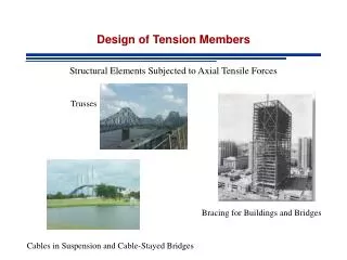
Simple Bolted Connections • There are different types of bolted connections. They can be categorized based on the type of loading. • Tension member connection and splice. It subjects the bolts to forces that tend to shear the shank. • Beam end simple connection. It subjects the bolts to forces that tend to shear the shank. • Hanger connection. The hanger connection puts the bolts in tension 68402/61420
Simple Bolted Connections P P Tension member Connection/ splice P P Beam end Simple shear connection 68402/61420
Simple Bolted Connections P P P Hanger connection (Tension) Moment resisting connection 68402/61420
Simple Bolted Connections • The bolts are subjected to shear or tension loading. • In most bolted connection, the bolts are subjected to shear. • Bolts can fail in shear or in tension. • You can calculate the shear strength or the tensile strength of a bolt • Simple connection: If the line of action of the force acting on the connection passes through the center of gravity of the connection, then each bolt can be assumed to resist an equal share of the load. • The strength of the simple connection will be equal to the sum of the strengths of the individual bolts in the connection. 68402/61420
Bolt Types & Materials A307 - Unfinished (Ordinary or Common) bolts low carbon steel A36, Fu = 413 MPa, for light structures under static load A325 - High strength bolts, heat-treated medium carbon steel, Fu = 827 MPa, for structural joints A490 - High strength bolts, Quenched and Tempered Alloy steel, Fu = 1033 MPa for structural joints A449 - High strength bolts with diameter > 1 ½”, anchor bolts, lifting hooks, tie-downs 68402/61420
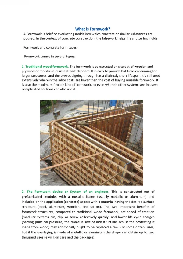
Common Bolts • ASTM A307 bolts • Common bolts are no longer common for current structural design but are still available 68402/61420
Slip Critical Bearing Type High Strength Bolts • High strength bolts (HSB) are available as ASTM A 325 and ASTM A490 Courtesy of Kao Wang Screw Co., Ltd. • Advantages of HSB over A307 bolts • Fewer bolts will be used compared to 307 è cheaper connection! • Smaller workman force required compared to 307 • Higher fatigue strength • Ease of bolt removal è changing connection 68402/61420
High Strength Bolts • Snug tight • All plies of the connection are in firm contact to each other: No pretension is used. • Easer to install and to inspect • Pre-tensioned • Bolts are first brought to snug tight status • Bolts are then tensioned to 70% of their tensile stresses Courtesy of www.halfpricesurplus.com • Bolts are tensioned using direct tension indicator, calibrated wrench or other methods (see AISC) • Slip critical • Bolts are pre-tensioned but surfaces shall be treated to develop specific friction. • The main difference is in design, not installation. Load must be limited not to exceed friction capacity of the connection (Strength Vs. Serviceability!) • Necessary when no slip is needed to prevent failure due to fatigue in bridges. 68402/61420
Type Type N Thread Type X Thread A325 330 413 A490 413 517 HSB – Bearing Type Connections • The shear strength of bolts shall be determined as follows AISC Table J3.2 The table bellow shows the values of fv (MPa) for different types of bolts • If the level of threads is not known, it is conservative to assume that the threads are type N. 68402/61420
Bolted Shear Connections • We want to design the bolted shear connections so that the factored design strength (Rn) is greater than or equal to the factored load. Rn Pu • So, we need to examine the various possible failure modes and calculate the corresponding design strengths. • Possible failure modes are: • Shear failure of the bolts • Failure of member being connected due to fracture or yielding or …. • Edge tearing or fracture of the connected plate • Tearing or fracture of the connected plate between two bolt holes • Excessive bearing deformation at the bolt hole 68402/61420
Failure Modes of Bolted Connections • Bolt Shearing • Tension Fracture • Plate Bearing • Block Shear 68402/61420
P P P P P P P/2 P/2 P P P/2 P/2 Actions on Bolt Shear, bearing, bending Bearing and single plane Shear Lap Joint Bending Bearing and double plane Shear Butt Joint 68402/61420
Single shear Double shear Bolted Shear Connections • Possible failure modes • Failure of bolts: single or double shear • Failure of connected elements: • Shear, tension or bending failure of the connected elements (e.g. block shear) • Bearing failure at bolt location 68402/61420
Bolted Shear Connections • Shear failure of bolts • Average shearing stress in the bolt = fv = P/A = P/(db2/4) • P is the load acting on an individual bolt • A is the area of the bolt and db is its diameter • Strength of the bolt = P = fv x (db2/4) where fv = shear yield stress = 0.6Fy • Bolts can be in single shear or double shear as shown above. • When the bolt is in double shear, two cross-sections are effective in resisting the load. The bolt in double shear will have the twice the shear strength of a bolt in single shear. 68402/61420
Bolted Shear Connections 68402/61420
Bolted Shear Connections • Failure of connected member • We have covered this in detail in this course on tension members • Member can fail due to tension fracture or yielding. • Bearing failure of connected/connecting part due to bearing from bolt holes • Hole is slightly larger than the fastener and the fastener is loosely placed in hole • Contact between the fastener and the connected part over approximately half the circumference of the fastener • As such the stress will be highest at the radial contact point (A). However, the average stress can be calculated as the applied force divided by the projected area of contact 68402/61420
Bolted Shear Connections • Average bearing stress fp = P/(db t), where P is the force applied to the fastener. • The bearing stress state can be complicated by the presence of nearby bolt or edge. The bolt spacing and edge distance will have an effect on the bearing strength. • Bearing stress effects are independent of the bolt type because the bearing stress acts on the connected plate not the bolt. • A possible failure mode resulting from excessive bearing close to the edge of the connected element is shear tear-out as shown below. This type of shear tear-out can also occur between two holes in the direction of the bearing load. Rn = 2 x 0.6 Fu Lc t = 1.2 Fu Lc t 68402/61420
Bolted Shear Connections • The bearing strength is independent of the bolt material as it is failure in the connected metal • The other possible common failure is shear end failure known as “shear tear-out” at the connection end Shear limitation Bearing limitation 68402/61420
Bolted Shear Connections 68402/61420
Bolted Shear Connections 68402/61420
Spacing and Edge-distance requirements • The AISC code gives guidance for edge distance and spacing to avoid tear out shear AISC Table J3.4 NOTE: The actual hole diameter is 1.6 mm bigger than the bolt, we use another 1.6 mm for tolerance when we calculate net area. Here use 1.6 mm only not 3.2 • Bolt spacing is a function of the bolt diameter • Common we assume • The AISC minimum spacing is 68402/61420
Bolt Spacings & Edge Distances • Bolt Spacings - Painted members or members not subject to corrosion: 2 2/3d≤ Bolt Spacings ≤ 24t or 305 mm (LRFD J3.3) (LRFD J3.5) - Unpainted members subject to corrosion: 3d≤ Bolt Spacings ≤ 14t or 178 mm • Edge Distance Values in Table J3.4M ≤ Edge Distance ≤ 12t or 152 mm (LRFD J3.4) (LRFD J3.5) d - bolt diameter t - thickness of thinner plate 68402/61420
Bolted Shear Connections • To prevent excessive deformation of the hole, an upper limit is placed on the bearing load. This upper limit is proportional to the fracture stress times the projected bearing area Rn = C x Fu x bearing area = C Fu db t • If deformation is not a concern then C = 3, If deformation is a concern then C = 2.4 • C = 2.4 corresponds to a deformation of 6.3 mm. • Finally, the equation for the bearing strength of a single bolts is Rn • where, = 0.75 and Rn = 1.2 Lc t Fu < 2.4 db t Fu • Lc is the clear distance in the load direction, from the edge of the bolt hole to the edge of the adjacent hole or to the edge of the material 68402/61420
Bolted Shear Connections • This relationship can be simplified as follows: The upper limit will become effective when 1.2 Lc t Fu > 2.4 db t Fu i.e., the upper limit will become effective when Lc > 2 db If Lc < 2 db, Rn = 1.2 Lc t Fu If Lc > 2 db, Rn = 2.4 db t Fu Fu - specified tensile strength of the connected material Lc - clear distance, in the direction of the force, between the edge of the hole and the edge of the adjacent hole or edge of the material. t - thickness of connected material 68402/61420
Important Notes Lc – Clear distance 68402/61420
Design Provisions for Bolted Shear Connections • In a simple connection, all bolts share the load equally. 68402/61420
Design Provisions for Bolted Shear Connections • In a bolted shear connection, the bolts are subjected to shear and the connecting/connected plates are subjected to bearing stresses. 68402/61420
Design Provisions for Bolted Shear Connections • The shear strength of all bolts = shear strength of one bolt x number of bolts • The bearing strength of the connecting / connected plates can be calculated using equations given by AISC specifications. • The tension strength of the connecting / connected plates can be calculated as discussed in tension members. 68402/61420
AISC Design Provisions • Chapter J of the AISC Specifications focuses on connections. • Section J3 focuses on bolts and threaded parts • AISC Specification J3.3 indicates that the minimum distance (s) between the centers of bolt holes is 2.67. A distance of 3db is preferred. • AISC Specification J3.4 indicates that the minimum edge distance (Le) from the center of the bolt to the edge of the connected part is given in Table J3.4. Table J3.4 specifies minimum edge distances for sheared edges, edges of rolled shapes, and gas cut edges. 68402/61420
AISC Design Provisions • AISC Specification indicates that the maximum edge distance for bolt holes is 12 times the thickness of the connected part (but not more than 152 mm). The maximum spacing for bolt holes is 24 times the thickness of the thinner part (but not more than 305 mm). • Specification J3.6 indicates that the design tension or shear strength of bolts is FnAb • = 0.75 • Table J3.2, gives the values of Fn • Ab is the unthreaded area of bolt. • In Table J3.2, there are different types of bolts A325 and A490. 68402/61420
AISC Design Provisions • The shear strength of the bolts depends on whether threads are included or excluded from the shear planes. If threads are included in the shear planes then the strength is lower. • We will always assume that threads are included in the shear plane, therefore less strength to be conservative. • We will look at specifications J3.7 – J3.9 later. • AISC Specification J3.10 indicates the bearing strength of plates at bolt holes. • The design bearing strength at bolt holes is Rn • Rn = 1.2 Lc t Fu ≤ 2.4 db t Fu - deformation at the bolt holes is a design consideration 68402/61420
p p Edge distance p g Common bolt terminologies • A325-SC – slip-critical A325 bolts • A325-N – snug-tight or bearing A325 bolts with thread included in the shear planes. • A325-X - snug-tight or bearing A325 bolts with thread excluded in the shear planes. • Gage – center-to-center distance of bolts in direction perpendicular to member’s axis • Pitch – ...parallel to member’s axis • Edge Distance – Distance from center of bolt to adjacent edge of a member p 68402/61420
Ex. 6.1 - Design Strength • Calculate and check the design strength of the simple connection shown below. Is the connection adequate for carrying the factored load of 300 kN. 10 mm 120x15 mm 30 mm 60 mm 63 k 300 kN 30 mm 20 mm A325-N bolts 30 mm 60 mm 30 mm 68402/61420
Ex. 6.1 - Design Strength • Step I. Shear strength of bolts • The design shear strength of one bolt in shear = Fn Ab = 0.75 x 330 x p x 202/4000 = 77.8 kN • Fn Ab = 77.8 kN per bolt (See Table J3.2) • Shear strength of connection = 4 x 77.8 = 311.2 kN 68402/61420
Ex. 6.1 - Design Strength • Step II. Minimum edge distance and spacing requirements • See Table J3.4M, minimum edge distance = 26 mm for rolled edges of plates • The given edge distances (30 mm) > 26 mm. Therefore, minimum edge distance requirements are satisfied. • Minimum spacing = 2.67 db = 2.67 x 20 = 53.4 mm. (AISC Specifications J3.3) • Preferred spacing = 3.0 db = 3.0 x 20 = 60 mm. • The given spacing (60 mm) = 60 mm. Therefore, spacing requirements are satisfied. 68402/61420
Ex. 6.1 - Design Strength • Step III. Bearing strength at bolt holes. • Bearing strength at bolt holes in connected part (120x15 mm plate) • At edges, Lc = 30 – hole diameter/2 = 30 – (20 + 1.6)/2 = 19.2 • Rn = 0.75 x (1.2 Lc t Fu) = 0.75 x (1.2 x19.2 x15x400)/1000 = 103.7 kN • But, Rn ≤ 0.75 (2.4 db t Fu) = 0.75 x (2.4 x 20x15x400)/1000 = 216 kN • Therefore, Rn = 103.7 kN at edge holes. • At other holes, s = 60 mm, Lc = 60 – (20 + 1.6) = 38.4 mm. • Rn = 0.75 x (1.2 Lc t Fu) = 0.75x(1.2 x 38.4 x15 x400)/1000 = 207.4 kN • But, Rn ≤ 0.75 (2.4 db t Fu) = 216 kN. Therefore Rn = 207.4 kN 68402/61420
Ex. 6.1 - Design Strength • Therefore, Rn = 216 kN at other holes • Therefore, bearing strength at holes = 2 x 103.7 + 2 x 207.4 = 622.2 kN • Bearing strength at bolt holes in gusset plate (10 mm plate) • At edges, Lc = 30 – hole diameter/2 = 30 – (20 + 1.6)/2 = 19.2 mm. • Rn = 0.75 x (1.2 Lc t Fu) = 0.75 x (1.2 x 19.2 x 10 x 400)/1000 = 69.1 kN • But, Rn ≤ 0.75 (2.4 db t Fu) = 0.75 x (2.4 x 20 x 10 x 400)/1000 = 144 kN. • Therefore, Rn = 69.1 kN at edge holes. 68402/61420
Ex. 6.1 - Design Strength • At other holes, s = 60 mm, Lc = 60 – (20 +1.6) = 38.4 mm. • Rn = 0.75 x (1.2 Lc t Fu) = 0.75 x (1.2 x 38.4 x 10x 400)/1000 = 138.2 kN • But, Rn ≤ 0.75 (2.4 db t Fu) = 144 kN • Therefore, Rn = 138.2 kN at other holes • Therefore, bearing strength at holes = 2 x 69.1 + 2 x 138.2 = 414.6 kN • Bearing strength of the connection is the smaller of the bearing strengths = 414.6 kN 68402/61420
Ex. 6.1 - Design Strength Connection strength (fRn) > applied factored loads (gQ). 311.2 > 300 Therefore ok. • Only connections is designed here • Need to design tension member and gusset plate 68402/61420
P P P P Pe Pe e e Eccentrically-Loaded Bolted Connections Eccentricity in the plane of the faying surface Direct Shear + Additional Shear due to moment Pe CG CG Eccentricity normal to the plane of the faying surface Direct Shear + Tension and Compression (above and below neutral axis) 68402/61420
Forces on Eccentrically-Loaded Bolts Eccentricity in the plane of the faying surface LRFD Spec. presents values for computing design strengths of individual bolt only. To compute forces on group of bolts that are eccentrically loaded, there are two common methods: • Elastic Method: Conservative. Connected parts assumed rigid. Slip resistance between connected parts neglected. • Ultimate Strength Method (or Instantaneous Center of Gravity Method): Most realistic but tedious to apply 68402/61420
P P e Pe r3 r1 d1 d3 P/3 P/3 P/3 CG CG d2 r2 Forces on Eccentrically-Loaded Bolts with Eccentricity on the Faying Surface • Elastic Method Assume plates are perfectly rigid and bolts perfectly elastic rotational displacement at each bolt is proportional to its distance from the CG stress is greatest at bolt farthest from CG 68402/61420
Forces on Eccentrically-Loaded Bolts with Eccentricity on the Faying Surface MCG = Pe = r1d1 + r2d2 + r3d3 Since the force on each bolt is proportional to its distance from the CG: Substitute into eqn. for MCG: 68402/61420
H1 r1 d1 y1 V1 x1 CG Forces on Eccentrically-Loaded Bolts with Eccentricity on the Faying Surface • Total Forces in Bolt i: • Horizontal Component = • Vertical Component = 68402/61420
CG Ex. 6.3 – Eccentric Connections – Elastic Method Determine the force in the most stressed bolt of the group using elastic method P=140 kN e 125 mm Eccentricity wrt CG: e = 125 + 50 = 175 mm Direct Shear in each bolt: P/n = 140/8 = 17.5 kN Note that the upper right-hand and the lower right-hand bolts are the most stressed (farthest from CG and consider direction of forces) 100 mm 100 mm 100 mm 100 mm 68402/61420
Ex. 6.3 – Eccentric Connections – Elastic Method Additional Shear in the upper and lower right-hand bolts due to moment M = Pe = 140x175 = 24500 kN.mm: The forces acting on the upper right-hand bolt are as follows: The resultant force on this bolt is: 30.6 kN 10.2 kN 17.5 kN 68402/61420