On-Chip Photonic Communications for High Performance Multi-Core Processors
370 likes | 622 Vues
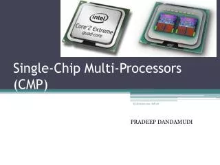
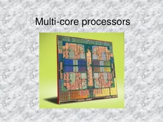
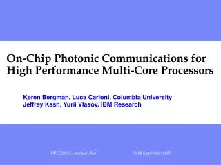
On-Chip Photonic Communications for High Performance Multi-Core Processors. Keren Bergman, Luca Carloni, Columbia University Jeffrey Kash, Yurii Vlasov, IBM Research. Chip MultiProcessors (CMP). CELL BE IBM 2005. Montecito Intel 2004. Terascale Intel 2007. Barcelona AMD 2007. Niagara

On-Chip Photonic Communications for High Performance Multi-Core Processors
E N D
Presentation Transcript
On-Chip Photonic Communications for High Performance Multi-Core Processors Keren Bergman, Luca Carloni, Columbia University Jeffrey Kash, Yurii Vlasov, IBM Research HPEC 2007, Lexington, MA
Chip MultiProcessors (CMP) CELL BE IBM 2005 Montecito Intel 2004 Terascale Intel 2007 Barcelona AMD 2007 Niagara Sun 2004 HPEC 2007, Lexington, MA
Networks on Chip (NoC) Shared, packet-switched, optimized for communications Resource efficiency Design simplicity IP reusability High performance But… no true relief in power dissipation Kolodny, 2005 HPEC 2007, Lexington, MA
Chip MultiProcessors (CMPs)IBM Cell, Sun Niagara, Intel Montecito, … IBM Cell: HPEC 2007, Lexington, MA
RX RX RX RX RX TX TX RX TX TX TX TX Why Photonics for CMP NoC? Photonics changes the rules for Bandwidth-per-Watt OPTICS: • Modulate/receive ultra-high bandwidth data stream once per communication event • Transparency: broadband switch routes entire multi-wavelength high BW stream • Low power switch fabric, scalable • Off-chip and on-chip can use essentially the same technology • Off-chip BW = On-chip BW for same power ELECTRONICS: • Buffer, receive and re-transmit at every switch • Off chip is pin-limited and really power hungry HPEC 2007, Lexington, MA
Recent advances in photonic integration Infinera, 2005 IBM, 2007 Lipson, Cornell, 2005 Bowers, UCSB, 2006 Luxtera, 2005 HPEC 2007, Lexington, MA
3DI CMP System Concept Processor System Stack • Future CMP system in 22nm • Chip size ~625mm2 • 3D layer stacking used to combine: • Multi-core processing plane • Several memory planes • Photonic NoC • For 22nm scaling will enable 36 multithreaded cores similar to today’s Cell • Estimated on-chip local memory per complex core ~0.5GB HPEC 2007, Lexington, MA
Optical NoC: Design Considerations • Design to exploit optical advantages: • Bit rate transparency: transmission/switching power independent of bandwidth • Low loss: power independent of distance • Bandwidth: exploit WDM for maximum effective bandwidths across network • (Over) provision maximized bandwidth per port • Maximize effective communications bandwidth • Seamless optical I/O to external memory with same BW • Design must address optical challenges: • No optical buffering • No optical signal processing • Network routing and flow control managed in electronics • Distributed vs. Central • Electronic control path provisioning latency • Packaging constraints: CMP chip layout, avoid long electronic interfaces, network gateways must be in close proximity on photonic plane • Design for photonic building blocks: low switch radix HPEC 2007, Lexington, MA
Goal: Design a NoC for a chip multiprocessor (CMP) Electronics Integration density abundant buffering and processing Power dissipation grows with data rate Photonics Low loss, large bandwidth, bit-rate transparency Limited processing, no buffers Our solution – a hybrid approach: A dual-network design Data transmission in a photonic network Control in an electronic network Paths reserved before transmission No optical buffering Photonic On-Chip Network P P P G G G P P P G G G P P P G G G HPEC 2007, Lexington, MA
P P P P P P P P P G G G G G G G G G Thin Electrical Control Network (~1% BW, small messages) Photonic NoC Deflection Switch On-Chip Optical Network ArchitectureBufferless, Deflection-switch based Cell Core (on processor plane) Gateway to Photonic NoC (on processor and photonic planes) HPEC 2007, Lexington, MA
Building Blocks (1): High-speed Photonic Modulator Ring Resonator • Ring-resonator structure • Achieve optical data modulation • Compact ~ 10mm diameter for high density integration • Ultra-low power ~ 1pJ/bit today, scalable to 0.1pJ/bit • 12.5Gb/s demo, extendable to 40Gb/s Recent 12.5GHz HPEC 2007, Lexington, MA
OFF ON Building Blocks (2): Broadband deflection switch • Broadband ring-resonator switch • OFF state • passive waveguide crossover • negligible power • ON state: • carrier injection coupling into ring signal switched ~0.5mW HPEC 2007, Lexington, MA
Building Blocks (3): Detector • Lateral PIN design, direct Ge growth on thin SOI (IBM) • Low capacitance and dark current • 20GHz Bandwidth • Ultra-low power, 0.1pJ/bit today scalable to 0.01pJ/bit HPEC 2007, Lexington, MA
4x4 Photonic Switch Element 4 deflection switches grouped with electronic control 4 waveguide pairs I/O links Electronic router High speed simple logic Links optimized for high speed Small area (~0.005mm2) Nearly no power consumption in OFF state HPEC 2007, Lexington, MA
Non-Blocking 4x4 Switch Design N N W E W E S S HPEC 2007, Lexington, MA • Original switch is internally blocking • Addressed by routing algorithm in original design • Limited topology choices • New design • Strictly non-blocking* • Same number of rings • Negligible additional loss • Larger area * U-turns not allowed
Design of strictly non-blocking photonic mesh Non-blocking 4x4 enables non-blocking mesh topology Network is strictly nonblocking (derived from crossbar) Link bidirectionality is exploited Allow 2 gateways to inject on each row Allow 2 gateways eject on each column Processor Layout May 18, 2007 HPEC 2007, Lexington, MA
electronic pathway electronic control 1 × 2 injection switch EC E/O modulators -mux drivers N EC electronic control logic W E receivers N -demultiplexer W S EC gw S EC gw EC Detailed layout gateway PSE network slice injection/ejection switch HPEC 2007, Lexington, MA
P P P P P P P P P P P P P P P P P P P P P P P P 6x6 tiled CMP Very large bandwidths per core Peak: 800 Gb/s Average: 512 Gb/s Compared designs Electronic on-chip network Hybrid photonic on-chip network Performance per Watt Comparative Power Analysis [DAC ’07] G G G G G G G G G G G G G G G G G G G G G G G G P P P P P P P P P P P P P P P P P P P P P P P P G G G G G G G G G G G G G G G G G G G G G G G G P P P P P P P P P P P P P P P P P P P P P P P P G G G G G G G G G G G G G G G G G G G G G G G G HPEC 2007, Lexington, MA
Electronic NoC Copper lines are bandwidth-limited Parallelism used to attain large bandwidth Wide busses and large buffers are power hungry Multiple hops require regeneration NoC power exceeding 100 W (prediction for 22 nm) Photonic NoC Message generation: 2.3 W (assuming 0.11 pJ/bit) Photonic switching: 0.04 W – practically negligible Network control: 0.8 W (and scaling down with technology) Total – 3.2 W optical I/O off-chip with same bandwidth to external memory at very little additional power. Power Analysis Results [DAC ’07] TX RX RX RX RX RX TX TX TX TX TX RX HPEC 2007, Lexington, MA
Performance Analysis • Goal to evaluate performance-per-Watt advantage of CMP system with photonic NoC • Developed network simulator using OMNeT++: modular, open-source, event-driven simulation environment • Modules for photonic building blocks, assembled in network • Multithreaded model for complex cores • Evaluate NoC performance under uniform random distribution • Performance-per-Watt gains of photonic NoC on FFT application HPEC 2007, Lexington, MA
Multithreaded complex core model • Model complex core as multithreaded processor with many computational threads executed in parallel • Each thread independently make a communications request to any core • Three main blocks: • Traffic generator – simulates core threads data transfer requests, requests stored in back-pressure FIFO queue • Scheduler – extracts requests from FIFO, generates path setup, electronic interface, blocked requests re-queued, avoids HoL blocking • Gateway – photonic interface, send/receive, read/write data to local memory HPEC 2007, Lexington, MA
Throughput per core • Throughput-per-core = ratio of time core transmits photonic message over total simulation time • Metric of average path setup time • Function of message length and network topology • Offered load considered when core is ready to transmit • For uncongested network: throughput-per-core = offered load • Simulation system parameters: • 36 multithreaded cores • DMA transfers of fixed size messages, 16kB • Line rate = 960Gbps; Photonic message = 134ns HPEC 2007, Lexington, MA
Throughput per core for 36-node photonic NoC Multithreading enables better exploitation of photonic NoC high BW Gain of 26% over single-thread Non-blocking mesh, shorter average path, improved by 13% over crossbar HPEC 2007, Lexington, MA
FFT Computation Performance • We consider the execution of Cooley-Turkey FFT algorithm using 32 of 36 available cores • First phase: each core processes: k=m/M sample elements • m = array size of input samples • M = number of cores • After first phase, log M iterations of computation-step followed by communication-step when cores exchange data in butterfly • Time to perform FFT computation depends on core architecture, time for data movement is function of NoC line rate and topology • Reported results for FFT on Cell processor, 224 samples FFT executes in ~43ms based on Bailey’s algorithm. • We assume Cell core with (2X) 256MB local-store memory, DP • Use Bailey’s algorithm to complete first phase of Cooley-Turkey in 43ms • Cooley-Turkey requires 5kLogk floating point operations, each iteration after first phase is ~1.8ms for k= 224 • Assuming 960Gbps, CMP non-blocking mesh NoC can execute 229 in 66ms HPEC 2007, Lexington, MA
FFT Computation Power Analysis • For photonic NoC: • Hop between two switches is 2.78mm, with average path of 11 hops and 4 switch element turns • 32 blocks of 256MB and line rate of 960Gbps, each connection is 105.6mW at interfaces and 2mW in switch turns • total power dissipation is 3.44W • Electronic NoC: • Assume equivalent electronic circuit switched network • Power dissipated only for length of optimally repeated wire at 22nm, 0.26pJ/bit/mm • Summary: Computation time is a function of the line rate, independent of medium HPEC 2007, Lexington, MA
FFT Computation Performance Comparison FFT computation: time ratio and power ratio as function of line rate HPEC 2007, Lexington, MA
Performance-per-Watt • To achieve same execution time (time ratio = 1), electronic NoC must operate at the same line rate of 960Gbps, dissipating 7.6W/connection or ~70X over photonic • Total dissipated power is ~244W • To achieve same power (power ratio = 1), electronic NoC must operate at line rate of 13.5Gbps, a reduction of 98.6%. • Execution time will take ~1sec or 15X longer than photonic HPEC 2007, Lexington, MA
Optical I/O Summary • CMPs are clearly emerging for power efficient high performance computing capability • Future on-chip interconnects must provide large bandwidth to many cores • Electronic NoCs dissipate prohibitively high power a technology shift is required • Remarkable advances in Silicon Nanophotonics • Photonic NoCs provide enormous capacity at dramatically low power consumption required for future CMPs, both on- and off-chip • Performance-per-Watt gains on communications intensive applications HPEC 2007, Lexington, MA
P P P P P P P P P P P P G G G G G G G G G G G G P P P P P P P P P P P P G G G G G G G G G G G G E per hop Link utilization P P P P P P P P P P P P G G G G G G G G G G G G Total Network Power Power Analysis: Electronic On-chip Network • Assumptions: • 6x6 Mesh, uniform traffic • Link length (l): 1.67 mm • Bus width (w): 168 bits • Signaling rate (f): 5 GHz • Injection rate (IR): 0.625 • Results: • Peak bandwidth (BWPEAK=wf) : 840 Gb/s • Average bandwidth (BWAVG=wfIR) : 525 Gb/s • Link traversal energy: • Elink= 0. 34 pJ/bit/mm (estimated for 32 nm) • Erouter= 0.83 pJ/bit (estimated for 32 nm) • Eflit-hop = (Elinkl+Elink) w = 235 pJ • 6x6 Mesh 120 links • Average link utilization (uniform traffic) = 0.75 Total network power = UAVG NLINKSEflit-hopf = 106 W
P P P P P P P P P P P P G G G G G G G G G G G G P P P P P P P P P P P P G G G G G G G G G G G G P P P P P P P P P P P P G G G G G G G G G G G G Power Analysis:(1) Photonic Network • 6x6 CMP (36 Gateways) • 12x12 Photonic mesh • 960 Gb/s peak bandwidth • Injection rate: 0.6 • Average BW: 576 Gb/s • 4 turns per message • 86 switches ON ( 0.5 mW each) • Network power: 43 mW
RX RX RX RX RX TX TX RX TX TX TX TX Power Analysis:(2) Photonic Gateways • Generating/receiving very high bandwidths is costly. • Comparable to a single electronic link • But – need to modulate/detect only once, while routing is nearly free.
P P P P P P P P P P P P G G G G G G G G G G G G P P P P P P P P P P P P G G G G G G G G G G G G P P P P P P P P P P P P G G G G G G G G G G G G Power Analysis:(3) Electronic Control Network • Low bandwidth electronic NoC:Carries only control packets. • Bulk of data transmitted on photonic network • Assumptions • x2 path length (overprovisioning) • 64 control bits per 2-KByte photonicmessage • Carries only 0.8% of the traffic • P = PElectronic-NoC 0.8% = 106 W 0.8% • Electronic control layer 0.82 W • Will scale down with electronic technology