Integrated Development Environment for Working with Models ARD
This project presents an Integrated Development Environment (IDE) tailored for model design and validation, focusing on class diagrams in Unified Modeling Language (UML). It aims to enhance feedback during the design process, allowing developers to create consistent and error-free models. With features like automatic pattern recognition for inconsistencies and a user-friendly graphical editor, the IDE ensures that designers can manage complex modeling tasks efficiently. Deployed as an Eclipse plug-in, it leverages UML2 and EMF frameworks to facilitate a robust modeling experience.

Integrated Development Environment for Working with Models ARD
E N D
Presentation Transcript
Integrated Development Environment for Working with ModelsARD Barak Agiv Itamar Ben-Zaken Barak Nahum VladislavSmolensky Academic Advisor: Yuval Elovici Professional Advisor: Mira Balaban
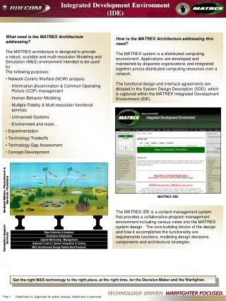
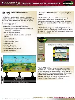
Vision To construct an Integrated Development Environment (IDE) for working with models • Providing feedback on the design • Providing modeling tools for the design process
The Problem Domain • Modeling is an essential step in the design process of many systems • A common model is a structural model – depicts the structure of a system, rather than the behavior • A common notation is the Class Diagram in the Unified Modeling Language (UML)
The Problem Domain Cont. • Class Diagrams allow significant expressive power,but also allow the creation of redundant, inconsistent and incorrect models • Designers are human – they make mistakes (e.g. lack of experience, complex models, merging several models) • Most UML Editors offer visualization of the model, and syntactic restrictions – but not semantic restrictions
Software Context • Deployed as an Eclipse plug-in • Feedback given in Problems View, graphical editor, dialogs
Software Interfaces • UML2Tools – graphical editors for UML diagrams • UML2 – an EMF-implementation of the UML meta-model • EMF (Eclipse Modeling Framework) – a meta-modeling framework Framework Framework
Extract Interface – An Example • A class diagram before refactoring:
Extract Interface • In order to perform the Extract Interface refactoring we will need to: • Create the interface • Create the generalization between the class and the interface • Move the operations of the class to the interface • Update association ends that pointed to the class to now point to the interface
Patterns Recognition - Examples • Hierarchy Cycle • Diamond Pattern
Patterns Recognition - Examples • Redundancy
Non-Functional Requirements • Verifying a model against an inconsistency pattern should take TBD seconds • The system will be able to handle a model with up to 2500 elements • Defining and registering a new template will be done visually • The system should be responsive at any time • Background processes can be aborted at any time
Model Verification Against Registered Patterns • Primary actors: Simple Modeler • Description: The modeler validates the model and looks for an inconsistency pattern. He can also choose to look for many/all the existing inconsistency patterns. • Trigger: The modeler wants to check the consistency of the model • Pre-conditions: none • Post-conditions: All the found patterns are shown to the modeler • Flow of events: 1. The modeler chooses the patterns he want to look for 2. The modeler starts the search 3. The system directs the modeler to the matched patterns • Alternative flows: None • Covered Requirements: Verifying a model against registered inconsistency-patterns