Download
1 / 29
290 likes | 306 Vues
An update on Power Pulsing with SDHCAL. Kieffer Robert IPN Lyon « CALICE collaboration meeting » May 2011, CERN. Outline. Intro: SDHCAL Part I: The power pulsing with HARDROCs Part II: Beamtest under B field @ CERN Conclusion. SDHCAL. Absorber: 2 cm thick iron plates

E N D
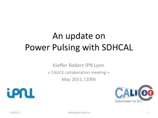
An update on Power Pulsing with SDHCAL Kieffer Robert IPN Lyon « CALICE collaboration meeting » May 2011, CERN kieffer@ipnl.in2p3.fr
Outline • Intro: SDHCAL • Part I: The power pulsingwithHARDROCs • Part II: Beamtestunder B field @ CERN • Conclusion kieffer@ipnl.in2p3.fr
SDHCAL • Absorber: 2 cm thick iron plates • Each sensitive cassette contains a readout boardstick to a GRPC. • Total (barrel + end caps): 50 millions readout channels (1x1cm2) • HARDROC power dissipation: 7.5 μW/channel (using power pulsing) • =>375 W for the whole SDHCAL very front end boards. • Detector interface cards located on border sides host FPGAs: these cards will probably need active cooling or the use of specific power pulsed ASICs to operate data transfer tasks. kieffer@ipnl.in2p3.fr
SDHCAL power pulsing test ASU Redout board 1536 channels The active sensitive unit: DIF • The readout board hosting 24 chips connected through a daisy chain scheme is controled by a DIF (detector interface) • This board is fixed on a 50x33 cm2 GRPC detector. • A non-magnetic metallic cassette contains this assembly. kieffer@ipnl.in2p3.fr
SDHCAL power pulsing principle 1 event 5 events 3 events 0 event 0 event Chip 0 Chip 1 Chip 2 Chip 3 Chip 4 Data bus • Readout architecture common to all calorimeters -> minimization of data lines & power • Daisy chain using token ring mode • Open collector, low voltage signals • Low capacitance lines Courtesy : N.Seguin Moreau LAL DAQ IDLE MODE Chip 0 Acquisition IDLE DAQ IDLE MODE Chip 1 Acquisition IDLE IDLE MODE Chip 2 Acquisition IDLE IDLE MODE Chip 3 Acquisition IDLE DAQ IDLE MODE Chip 4 Acquisition 1ms (.5%) .5ms (.25%) 198ms (99%) 1% duty cycle 99% duty cycle kieffer@ipnl.in2p3.fr
Power Pulsing in HARDROC • Shut down biascurrents and reference voltages withvdd: ALWAYS ON • Bandgap + otherref voltages + master I : POWER PULSED ON/OFF • 3 Power pulsinglinesused: Anlog, ADC, Digital • Each stage canbe power pulsed (or not) by setting ON/OFF the related slow control shift registers. Slow control shift registers Analog power line ADC power line kieffer@ipnl.in2p3.fr
Power lines sequence Idle Idle READOUT 4ms/chip Abs. Max. ACQUISITION Power analog. (DAQ) Power DAC (DAQ) Power digital (DAQ) Controled by the DIF Power digital (POD) POD module • The Power On Digital manage the LVDS buffers to provide clock signal only when needed. • When the StartReadout comes from the daisy chain loop to trigger the data transfer, Power digital line is automatically switched ON by the POD. kieffer@ipnl.in2p3.fr
Power consomption on HARDROC • ILD Requirement: • 10 µW/ch with 0.5% duty cycle • 200 µA for the entire chip (64 channels) Power consomption of each part Power consomption setting up the tree power lines: Anlog, ADC, Digital • HR2 power consomption measurement: • 29 mA x 3.3V ≈ 100 mW => 1.5 mW/ch • 7.5 µW/chwith 0.5% duty cycle kieffer@ipnl.in2p3.fr
Power pulsing under testbeam conditions kieffer@ipnl.in2p3.fr
A testbeam under B field Power pulsing test beam June 2010: 10 days, SPS H2, parasitic operation Beam conditions: 80GeV @ High Rate Aim: PowerPulsing tests using B field. PowerPulsed events: 42 kEvents Non-PowerPulsed events: 74 kEvents 32x48 cm2 GRPC Beam B field Beam I Current (Power Pulsing) 3T Magnet kieffer@ipnl.in2p3.fr
Power pulsing cycle First tests with B field Power On Period: 10ms (100 Hz) DutyCycle: 2/10 2 ms Data taking Δt Enable Acquisition Waking time 100 μs Trigger for chip readout Trigger Pulse Generator 2ms/10ms Power On Injecting on falling edge through a 2pC build in capacitor ASU Scintillator Coincidence & Trigger DIF « In Spill » Signal Veto From Acquisition kieffer@ipnl.in2p3.fr Busy
Data time structure no Power Pulsing Time to trigger spectra 400ns Clockperiod: Time selection for triggeredevents: Noise contamination ratio: Signal+Noise Noise 0<EvTime<1.2us 1% Time to external trigger in clock counts kieffer@ipnl.in2p3.fr
Efficiencywith power pulsing First tests with B field About 4% efficiency loss! Remember my talk @ CALICE CASBALANCA 3T B field Preliminary kieffer@ipnl.in2p3.fr
Digging into the data to understand Two kind of Bcid: Signal+Noise ? A suspicious behaviour as been pointed out in the time to trigger distribution using power pulsing! Noise Signal+Noise? Digging in the DIF’s FPGA firmware we found the reason of this double peak structure! Time to external trigger in clock counts In the HARDROC, there is a double latch procedure applied on the reset BCid (timing flag) if it append with start_acquisition up: this is the classical scheme (right peak). On each power cycle, the first trigger is recorded without these 3 clock count because the reset happen before the start_acquisition command is up (left peak). kieffer@ipnl.in2p3.fr
Digging into the data to understand Double latch on reset Reset Direct In the HARDROC, there is a double latch procedure applied on the reset BCid (timing flag) if it append with start_acquisition up: this is the classical scheme (right peak). On each power cycle, the first trigger is recorded without these 3 clock count because the reset happen before the start_acquisition command is up and is not double latched(left peak). kieffer@ipnl.in2p3.fr
Digging into the data to understand First tests with B field The main source off efficiency loss As we ran at hight rate, some triggers have been taken by the DIF right after the Enable_acqsignal. As the trigger is coming from PM coinc, it is related to a particle who have passed just before when the chip was sleeping. This external trigger actually force the readout, but there is no data in the chip to be readed out. => These no data triggers where thought as inefficient triggers an we lost efficiency. Space cut in data to be shure Only the hits found in the beam area are taken in account as good events for efficiency studies. 20 cm Cut Position Y (cm) 13 cm Cut Position X (cm) kieffer@ipnl.in2p3.fr
Efficiency using Power Pulsing First tests with B field 3T B field Now we can say that: No efficiency loss is found runing under power pulsing. kieffer@ipnl.in2p3.fr
Timing of power cycle in the data First tests with B field Trigger taken in two consecutive power-cycles (10ms) One cycle without trigger (20ms) Two cycles without trigger… Gaussian fit sigma: ±0.84 ms <=> Power on 2ms Up to 11 power-cycles acquiring during a spill !!! Trigger taken in the same power-cycle (2ms) kieffer@ipnl.in2p3.fr
Summary First tests with B field Up to now: • Power pulsing scheme validated in testbeam with SDHCAL prototype, and the data is now well understood. -> Most of the problems cames from DIF’s firmare and are now corrected. • Power consumption matches our goals: 7.5 μW/channel Next: • Publish a paper about these interesting results. • Go to a large scale prof of power pulsing: maybe on SDHCAL physical protoype in a second period. • (SDHCAL under construction: testbeam scheduled June 2011) kieffer@ipnl.in2p3.fr
Backup slides kieffer@ipnl.in2p3.fr
Injection with power pulsing First tests with B field 2.15 ms Power On T: 100ms DutyCycle 2/100 Data taking 2 ms Δt Enable Acquisition Waking time 100 μs Trigger Trigger for chip readout Charge injection on falling edge Injection kieffer@ipnl.in2p3.fr
Injection with power pulsing First tests with B field 2.15 ms Power On T: 100ms DutyCycle 2/100 Data taking 2 ms Δt Enable Acquisition Waking time 100 μs Trigger for chip readout Dual Pulse Generator 1:Power cycle 2:Enable cycle Power On ASU Injecting on falling edge through a 2pC build in capacitor Enable Synchro DIF Dual Pulse Generator 1:Injection edge2: Trigger Injection Trigger kieffer@ipnl.in2p3.fr
PWR ON PWR ON FSB0 8 µs Trigger 25 µs DAC output (Vth) POWER PULSING: « AWAKE TIME » • Power pulsing of the 10 bit-DAC: • 25 µs (slew rate limited) • All decoupling capacitors removed on bias voltages • PWR ON: ILC like (1ms,199ms) • PP of the analog part: • Input signal synchronised on PWR ON • Awake time= 8 µs kieffer@ipnl.in2p3.fr
Injection with power pulsing First tests with B field Preliminary Injectingdifferent charges with a constant threshold, giveroughly a DAC/Charge value for HARDROC 2B. => 140 DAC ≈ 0.53 pC (on Threshold_0) kieffer@ipnl.in2p3.fr
Injection with power pulsing First tests with B field Wewill use this point Charge: 0.54 pC Eff: 96.4% To check time stability. Preliminary Injectingdifferent charges with a constant threshold, giveroughly a DAC/Charge value for HARDROC 2B. => 140 DAC ≈ 0.53 pC (on Threshold_0) kieffer@ipnl.in2p3.fr
Injection with power pulsing First tests with B field Suspectingthresholdstability, weinjected charges withdifferentdelaysfromPower-ONedge. Efficiencyisquite constantduring the 2ms power cycle. Workisstillongoingto understandefficiencylossrecorded on beam data. Preliminary kieffer@ipnl.in2p3.fr
Preliminary tests using B field First tests with B field No Power Pulsing Is B field having an effect on cluster shape? kieffer@ipnl.in2p3.fr
Preliminary tests using B field B field has no impact on efficiency. No Power Pulsing kieffer@ipnl.in2p3.fr
Preliminary tests using B field No Power Pulsing B fieldincreasea bit the multiplicity. kieffer@ipnl.in2p3.fr